Pico裸机4(Hello World!)
1 UART协议
其实在MCU上面,Hello World一般是点灯,只是我是软件出身,还是把Hello World列为一个里程碑吧。。。
要在Pico上实现输出Hello World,一般还是Uart输出,也就是我们一般说的串口输出。关于Uart,可以参考之前的文章:https://blog.csdn.net/fanged/article/details/140913847
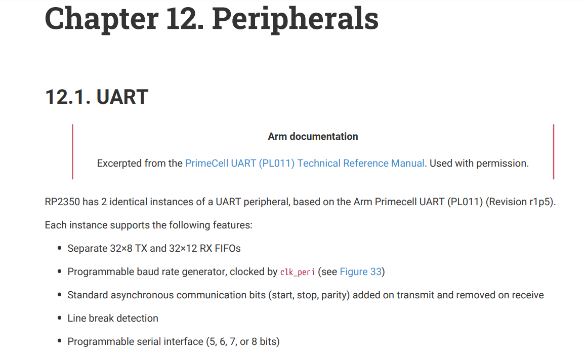
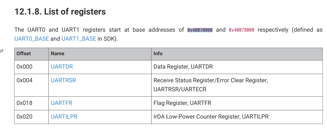
要在Pico上实现Uart,除了了解UART协议本身,还有就是了解在rp2350的配置方法。在数据手册上是在12章。
内容很多,我这方面经验也不多,直接看后面代码吧。
2 代码
代码还是来自之前的大神:https://github.com/carlosftm/RPi-Pico2-Baremetal/tree/main/02_BlockingUART
环境是之前文章所搭建的环境。https://blog.csdn.net/fanged/article/details/155830094
/* Copyright (c) 2024 CarlosFTM
SPDX-License-Identifier: GPL-3.0-or-later
(see LICENSE.txt for details)
*/
#include <stdint.h>
/* Define register access function
To make the code more readable, we make use of these macros */
#define PUT32(address, value) (*((volatile unsigned int *)(address))) = value
#define GET32(address) (*(volatile unsigned int *)(address))
/* Define Atomic Register Access
See section 2.1.3 "Atomic Register Access" on RP2350 datasheet */
#define WRITE_NORMAL (0x0000) // normal read write access
#define WRITE_XOR (0x1000) // atomic XOR on write
#define WRITE_SET (0x2000) // atomic bitmask set on write
#define WRITE_CLR (0x3000) // atomic bitmask clear on write
/* Function declaration */
int main( void );
void Default_Handler(void);
void Reset_Handler(void);
/* Type definitions */
typedef void(*vectors_t)(void);
typedef struct {
uint32_t word0;
uint32_t word1;
uint32_t word2;
uint32_t word3;
uint32_t word4;
} PicobinBlockItem;
/* Extern Variables */
extern unsigned int __stack_end__;
/* Vector Table */
__attribute__( ( used, section( ".vector_table" ) ) ) vectors_t vectorTable[] =
{
(vectors_t)(&__stack_end__), // Initial SP
Reset_Handler, // Reset
Default_Handler, // NMI
Default_Handler, // HardFault
Default_Handler, // MemManage
Default_Handler, // BusFaults
Default_Handler, // UsageFault
0, // Reserved
0, // Reserved
0, // Reserved
0, // Reserved.
Default_Handler, // SVCall
Default_Handler, // DebugMonitor
0, // Reserved
Default_Handler, // PendSV
Default_Handler, // SysTick
Default_Handler, // IRQ0
Default_Handler, // IRQ1 ...
};
/* RP2350 Spec - 5.9.5. Minimum Viable Image Metadata
As we want to work with ARM Arch, then we use the Minimum Arm IMAGE_DEF
*/
PicobinBlockItem picoBinBlockItem __attribute__((section(".picobin_block_item"))) = {
.word0 = 0xffffded3, // PICOBIN_BLOCK_MARKER_START (4 byte magic header)
.word1 = 0x10210142, // 0x42 PICOBIN_BLOCK_ITEM_1BS_IMAGE_TYPE, 0x01 word in size, 0x1021 image type exe secure, ARM, RP2350
.word2 = 0x000001ff, // 0x00 pad, 0x0001 size, 0xff(size_type == 1, item_type_ == PICOBIN_BLOCK_ITEM_2BS_LAST)
.word3 = 0x00000000, // loop containing just this block
.word4 = 0xab123579, // PICOBIN_BLOCK_MARKER_END (4 byte magic footer)
};
void Default_Handler(void)
{
while (1)
{
asm("nop");
}
}
void Reset_Handler(void)
{
uint32_t cpuId = GET32(0xd0000000);
if (cpuId == 1)
{
// Hold Core1 on infinite loop
while(1)
{
asm("nop");
}
}
main();
}
/* Delay Function
5 instructions are needed to do a loop. Therefore:
5 loops @ 12MHz = 2398 clock cycles per ms.
*/
void delay(uint32_t millisec)
{
for(uint32_t i = 0; i < millisec * 2398; i++)
{
asm("nop");
}
}
/* ConfigDevice Function
Configures the clock and GPIO
*/
void configDevice(void)
{
// Setup XOC clock to drive the GPIO (Pico2 board as a ABM8-272-T3 crystal that oscillates at 12MHz)
PUT32((0x40048000 + 0), 0x00000aa0); // XOC range 1-15MHz (Crystal Oschillator)
PUT32((0x40048000 + 0x0c), 0x000000c4); // Startup Delay (default = 50,000 cycles aprox.)
PUT32((0x40048000 + 0x2000), 0x00FAB000); // Enable XOC
while (!(GET32(0x40048000 + 4) & ( 1 << 31 ))); // Wait for XOC stable
// Configure source clock for components (see datasheer RP2350 Chapter 8. "Clocks")
PUT32((0x40010000 + 0x3C), 0 ); // CLK SYS CTRL = XOC (for processor, bus frabric & memories)
PUT32((0x40010000 + 0x48), ((1 << 11) | ( 4 << 5))); // CLK_PERI_CTRL = XOC (for perifery UART and SPI) + Enable
// De-asserts the reset of UART0
PUT32((0x40020000 + WRITE_SET + 0x0), (1 << 26)); // Set UART0 to reset
asm("nop");
asm("nop");
PUT32((0x40020000 + WRITE_CLR + 0x0), (1 << 26)); // De-assert the reset from UART0
while (!(GET32(0x40020000 + 0x08) & (1 << 26))); // Wait for UART0 to be ready
// Configure GPIO25 to use function 5 (SIO) to controll the GPIO by software
PUT32((0x40028000 + 0xcc), 5); // IO GPIO25 uses SIO
PUT32((0x40028000 + 0x04), 2); // IO GPIO0 uses UART TX
PUT32((0x40028000 + 0x0c), 2); // IO GPIO1 uses UART RX
// Enable GPIO out in SIO register
PUT32((0xd0000000 + WRITE_SET + 0x038), (1 << 25)); // SIO OE (output enable) for Pin25
// Configure the pad control (new on RP2350)
PUT32((0x40038000 + WRITE_CLR + 0x68), (1 << 8)); // Remove GPIO25 pad isolation
PUT32((0x40038000 + WRITE_CLR + 0x04), (1 << 8)); // Remove UART0TX pad isolation
PUT32((0x40038000 + WRITE_CLR + 0x08), (1 << 8)); // Remove UART0RX pad isolation
PUT32((0x40038000 + WRITE_SET + 0x08), (1 << 6)); // Enable UART0RX pad for input
// Configure UART0
// Baud: For a baud rate of 115200 with UARTCLK = 12MHz then:
// Baud Rate Divisor = 12000000/(16 * 115200) ~= 6.5104
PUT32((0x40070000 + 0x24), 6); // UARTIBRD_H: Integer part of the baudrate divisor
PUT32((0x40070000 + 0x28), 5104); // UARTFBRD_L: Decimal part of the baudrate divisor
PUT32((0x40070000 + 0x2c), (( 0x3 << 5 ) | ( 1 << 4 ))); // UARTLCR_H: Word lenght = 8, FIFO RX/TX enabled
PUT32((0x40070000 + 0x30), (( 1 << 9 ) | ( 1 << 8 ) | ( 1 << 0 ))); // UARTCR: UART Enabled, Tx enabled, Rx enabled
}
/* Transmits Character over UART
Writes a character on the UART TX FIFO
*/
void uartTxChar(int8_t txData)
{
volatile int8_t myData = txData;
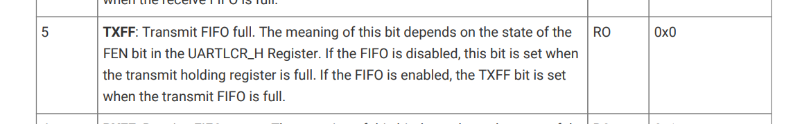
while(GET32(0x40070000 + 0x018) & (1 << 5)); // Wait until UART0 FIFO is empty
PUT32((0x40070000 + 0x0), myData); // UARTDR: Write data to Tx.
}
/* Transmits string over UART
Writes a character on the UART TX FIFO
*/
void uartTxString(int8_t* txData)
{
while(*txData != '\0')
{
uartTxChar(*txData++);
}
uartTxChar('\r');
uartTxChar('\n');
}
/* Indicates when data is avaiable on UART Rx FIFO
*/
int uartRxDataAvail(void)
{
return ((GET32(0x40070000 + 0x018) & (1 << 4)) == 0); // Wait until UART0 FIFO is no empty
}
/* Receives character over UART
*/
uint8_t uartRxChar(void)
{
while(uartRxDataAvail() == 0); // Wait until UART0 Rx data is available
return((unsigned char)GET32(0x40070000 + 0x0)); // UARTDR: Write data to Tx.
}
/* -------------
Main Function
-------------
*/
int main( void ){
configDevice();
delay(1000);
uartTxString((int8_t*)"-= UART Blocking Example for RP2350 =-\n\n");
while(1)
{
unsigned char i = '0';
int8_t textString[] = "[ ] Hola Mundo!";
while(i <= 'Z')
{
textString[1] = i++;
uartTxString(textString);
PUT32((0xd0000000 + WRITE_SET + 0x028), (1 << 25)); // xor GPIO (toggle pin)
delay(100);
if (uartRxDataAvail() != 0)
{
uartTxChar(uartRxChar()); // Transmit each received character
}
}
}
return 0;
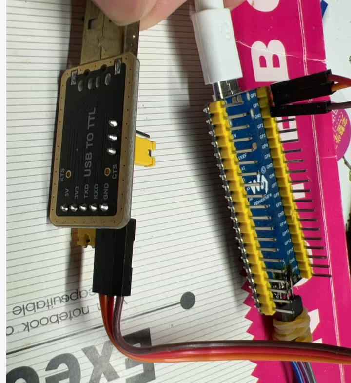
}使用的UART0,也就是右上角两个口,再加上一个GND。再找一个TTL转USB。
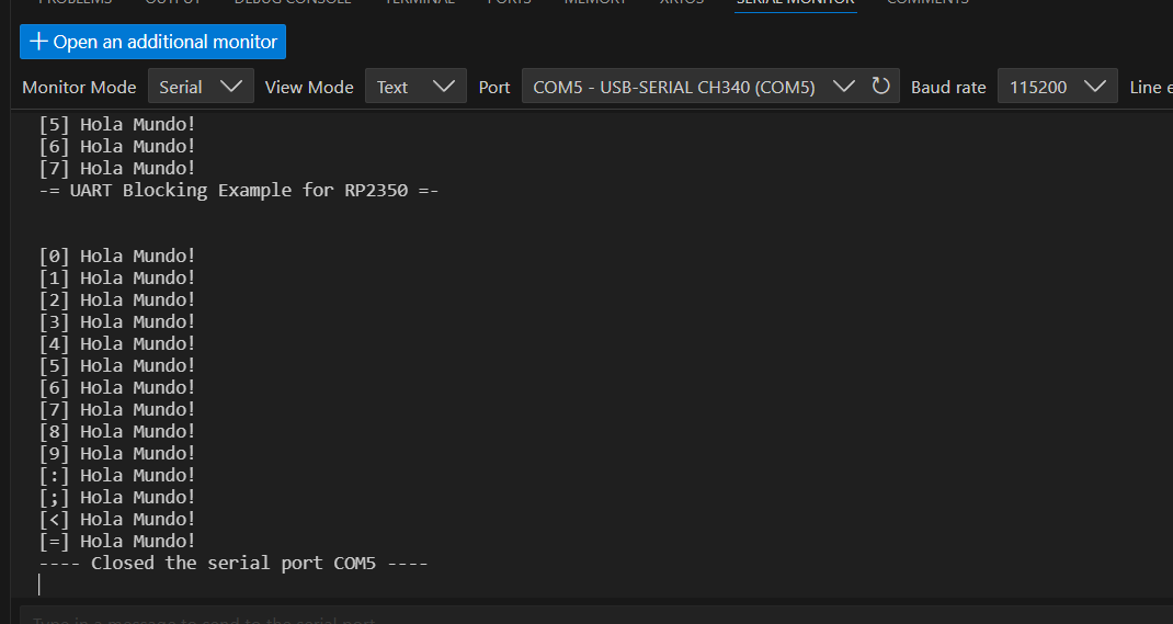
接好后直接用PICO插件的串口工具,很快就出结果了。。
3 代码学习
3.1 初始化
就是在configDevice()中操作的。去掉了时钟初始化和LED的部分代码如下:
// De-asserts the reset of UART0
PUT32((0x40020000 + WRITE_SET + 0x0), (1 << 26)); // Set UART0 to reset
asm("nop");
asm("nop");
PUT32((0x40020000 + WRITE_CLR + 0x0), (1 << 26)); // De-assert the reset from UART0
while (!(GET32(0x40020000 + 0x08) & (1 << 26))); // Wait for UART0 to be ready
// Configure GPIO25 to use function 5 (SIO) to controll the GPIO by software
PUT32((0x40028000 + 0x04), 2); // IO GPIO0 uses UART TX
PUT32((0x40028000 + 0x0c), 2); // IO GPIO1 uses UART RX
// Configure the pad control (new on RP2350)
PUT32((0x40038000 + WRITE_CLR + 0x04), (1 << 8)); // Remove UART0TX pad isolation
PUT32((0x40038000 + WRITE_CLR + 0x08), (1 << 8)); // Remove UART0RX pad isolation
PUT32((0x40038000 + WRITE_SET + 0x08), (1 << 6)); // Enable UART0RX pad for input
// Configure UART0
// Baud: For a baud rate of 115200 with UARTCLK = 12MHz then:
// Baud Rate Divisor = 12000000/(16 * 115200) ~= 6.5104
PUT32((0x40070000 + 0x24), 6); // UARTIBRD_H: Integer part of the baudrate divisor
PUT32((0x40070000 + 0x28), 5104); // UARTFBRD_L: Decimal part of the baudrate divisor
PUT32((0x40070000 + 0x2c), (( 0x3 << 5 ) | ( 1 << 4 ))); // UARTLCR_H: Word lenght = 8, FIFO RX/TX enabled
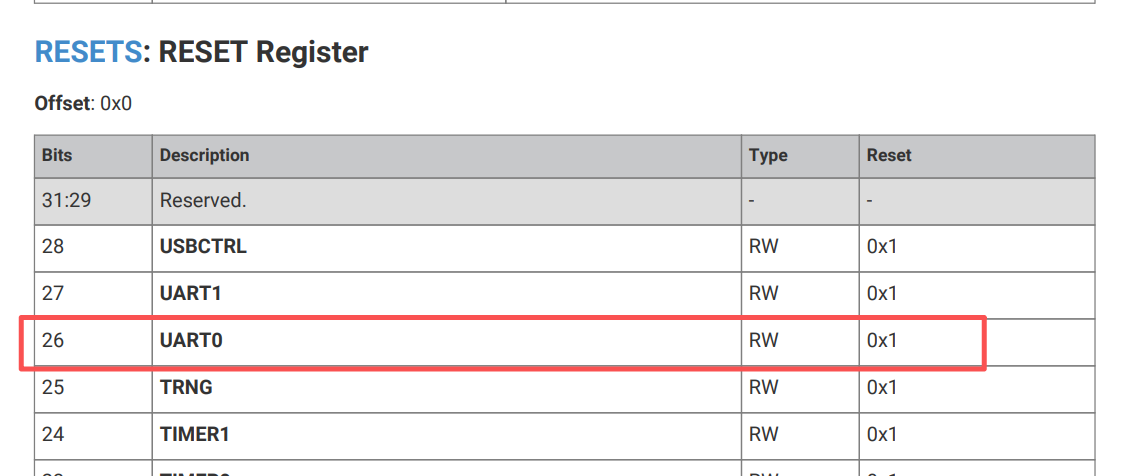
PUT32((0x40070000 + 0x30), (( 1 << 9 ) | ( 1 << 8 ) | ( 1 << 0 ))); // UARTCR: UART Enabled, Tx enabled, Rx enabled首先是初始化UART0,操作Rest寄存器的26位。中间使用asm("nop");短暂等待。
之后通过SIO的寄存器,将IO口配置成UART。
然后要显示配置pad isolation,这是树莓派pico安全低功耗的特性,总之要搞一下。
最后就是具体配置UART0,波特率,模式之类的。
3.2 发送和接收
首先是发送。将发送字符串封装成了一个函数。这个没什么好看的。
void uartTxString(int8_t* txData)
{
while(*txData != '\0')
{
uartTxChar(*txData++);
}
uartTxChar('\r');
uartTxChar('\n');
}
然后是发送字符。
void uartTxChar(int8_t txData)
{
volatile int8_t myData = txData;
while(GET32(0x40070000 + 0x018) & (1 << 5)); // Wait until UART0 FIFO is empty
PUT32((0x40070000 + 0x0), myData); // UARTDR: Write data to Tx.
}
首先用GET32检查FIFO的指示寄存器是否为空。
然后用PUT32将数据写入UART0的数据寄存器。
这里的UARTDR虽然是32位,0x00到0x03,但是只有低8位是有效数据位。所以一次只能写入一个char。
再看看接收。
/* Indicates when data is avaiable on UART Rx FIFO
*/
int uartRxDataAvail(void)
{
return ((GET32(0x40070000 + 0x018) & (1 << 4)) == 0); // Wait until UART0 FIFO is no empty
}
/* Receives character over UART
*/
uint8_t uartRxChar(void)
{
while(uartRxDataAvail() == 0); // Wait until UART0 Rx data is available
return((unsigned char)GET32(0x40070000 + 0x0)); // UARTDR: Write data to Tx.
}
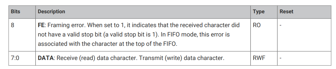
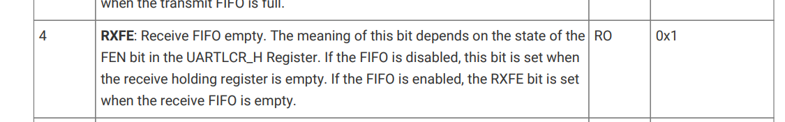
首先是查看是否有待读的数据。用来判断的是UARTFR Register的第4位。
之后从发送相同的数据寄存器,UARTDR读取数据。虽然只有一个char,但是这里读取也是用的GET32,好像是ARM结构UART的读取只能32位读。。。
这里还有一个问题。0x40070000 + 0x0,之前写操作也是这个地址,查了一下,好像是为了节约寄存器寻址空间,所以做成共用,但是硬件上做了区隔的。
好了,就到这里吧。。这也算比较简单的了,中断,DMA啥的都没有。后面再学习吧。。。

AtomGit 是由开放原子开源基金会联合 CSDN 等生态伙伴共同推出的新一代开源与人工智能协作平台。平台坚持“开放、中立、公益”的理念,把代码托管、模型共享、数据集托管、智能体开发体验和算力服务整合在一起,为开发者提供从开发、训练到部署的一站式体验。
更多推荐

 5
5 0
0- 0


 已为社区贡献4条内容

所有评论(0)