基于沁恒CH32V203与INA226的USBSS功率计项目(代码开源)
前言:本篇博客为手把手教学的基于 CH32V203 的 USB 功率计项目,项目使用的 MCU 为沁恒的 CH32V203C8T6 搭配 Qt Creator 制作上位机,Qt 的版本为 Qt 5.9.0,且作者额外提供本项目的硬件电路设计图。项目使用 TI 的 INA226 芯片进行 USB 器件负载的电流与功耗测量,通过 2.4 寸 LCD 与专属上位机 ikun Power Analyze 进行测量数据显示。下位机与上位机的数据传输利用 CH32V203 的 USBFS CDC 进行数据交互。希望这篇博文能给读者朋友的工程项目给予些许帮助,Respect(代码开源)!
硬件与软件:CH32V203C8T6、iKun Power Analyze、MounRiver Studio Ⅱ、嘉立创 EDA、Qt 5.9.0

一、ikun Power Analyze 功率计项目概述
1.1 USBSS 功率计概述
USB 功率计是串联在 USB 供电链路中的测量仪器,实时采集 VBUS 电压、电流并计算功率(P=U×I),兼顾快充协议监测、纹波捕捉与数据记录,是充电器 / 电源 / 负载研发、调试、质检与功耗分析的核心工具。USB 功率计应用场景包括:1、充电器性能测试;2、移动电源评测调试;3、手机 / 数码充电监测;4、嵌入式硬件开发调试;5、锂电池充电管理;
本项目 ikun Power Analyze 借鉴市面上主流的 USB 功率计设计,搭配专属上位机 ikun Power Analyze 拥有很好的嵌入式开发调试能力。本项目综合选用沁恒微 CH32V203C8T6 与德州仪器 INA226 作为核心元器件,保证测量精度与物料的性价比,非常适合广大读者朋友们进行 2 次复刻或者升级。
1.2 INA226 电子器件介绍
INA226 是德州仪器(TI)推出的一款16 位、超高精度、双向电流 / 电压 / 功率监测芯片,带 I2C/SMBus 数字接口与告警输出,可对 0~36V 系统做高侧 / 低侧电流检测,广泛用于电源管理、电池监测、服务器与工业控制等场景德州仪器。一句话:16 位、I2C 接口、可测 0–36V、高精度、能直接读电流 / 电压 / 功率的 “智能功率监测芯片”。
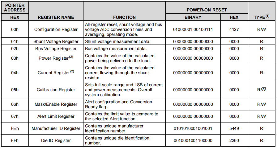
德州仪器 INA226 各关键寄存器的功能如下:
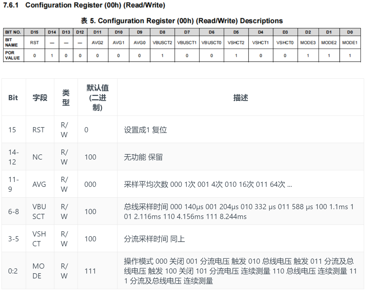
1、配置寄存器(00h,可读写):上电默认值为 0x4127,用于芯片全局设置,包括软复位、分流 / 总线电压的 ADC 转换时间、采样平均次数,以及芯片工作模式(如连续采样、单次采样或掉电模式),是初始化的关键。
2、分流电压寄存器(01h,只读):存储分流电阻两端的差分电压测量值,分辨率为 2.5μV/bit,需结合校准值才能换算为电流。
3、总线电压寄存器(02h,只读):存储被测总线电压的测量值,分辨率为 1.25mV/bit,可直接换算为负载供电电压。
4、功率寄存器(03h,只读):芯片内部根据总线电压和电流计算出的负载功率值,单位为 mW,无需外部 MCU 额外计算。
5、电流寄存器(04h,只读):芯片内部根据分流电压和校准值换算出的电流值,单位为 mA,依赖正确的校准配置才能得到准确结果。
6、校准寄存器(05h,可读写):核心校准寄存器,通过写入与分流电阻阻值匹配的校准值,设定电流和功率测量的量程与 LSB(最小分辨率),直接决定电流、功率读数的准确性。
7、屏蔽 / 使能寄存器(06h,可读写):用于配置报警功能(如过流、过压、过功率报警),并包含转换完成标志位,方便 MCU 判断数据是否就绪。
8、报警阈值寄存器(07h,可读写):设置对应报警功能的触发阈值,当测量值超过该阈值时,ALERT 引脚会触发相应信号。
9、厂商 ID 寄存器(FEh,只读):存储 TI 的唯一厂商识别号(固定为 0x5449),可用于芯片识别与通信验证。
10、芯片 ID 寄存器(FFh,只读):存储 INA226 的专属型号识别号(固定为 0x2260),可用于确认芯片型号是否正确。
1.3 ikun Power Analyze 功率计项目
本项目使用南京沁恒微电子有限公司 的 CH32V203C8T6 作为核心 MCU。南京沁恒微电子股份有限公司(WCH,Win Chip Head)是国内专注连接技术与 MCU的集成电路设计企业,以自研 IP + 一体化芯片为核心竞争力。自研青稞 RISC-V 内核与 USB、以太网、蓝牙核心 IP,主打沁恒 CH 系列单片机、USB 转接芯片。 产品性价比高、资料齐全、生态成熟,广泛用于工控、物联网、数码外设,是国产嵌入式主流选型。

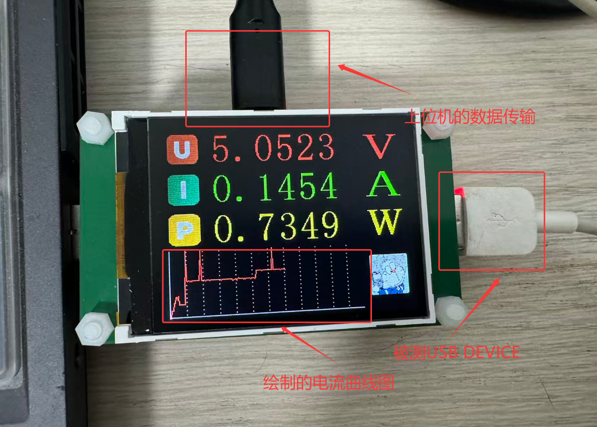
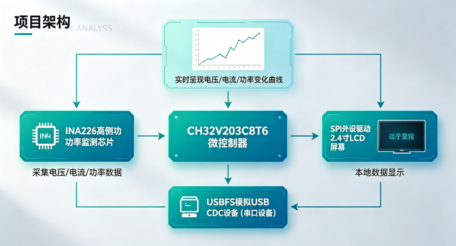
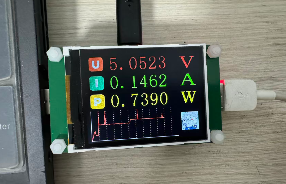
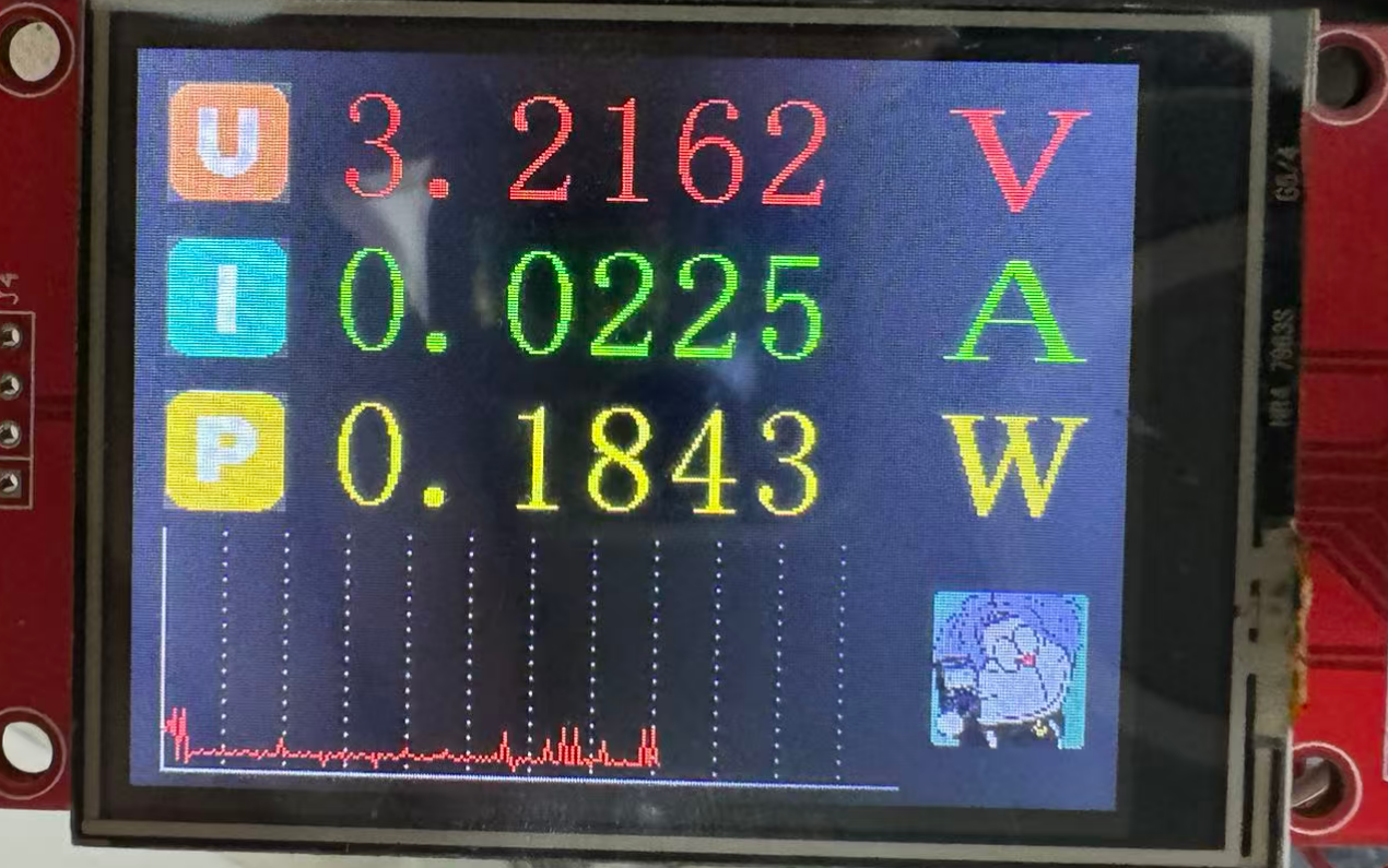
本项目基于 CH32V203C8T6 微控制器,通过 INA226 高侧功率监测芯片采集电压、电流及功率数据,并利用 SPI 外设驱动 2.4 寸 LCD 屏幕进行本地数据显示。同时,利用 CH32V203 的 USBFS 模拟 USB CDC 设备(串口设备),并与上位机 ikun Power Analyze 建立数据交互。上位机软件接收下位机发送的采样数据后,以动态折线图的形式实时呈现电压、电流及功率的变化曲线。
二、ikun Power Analyze 的硬件设计
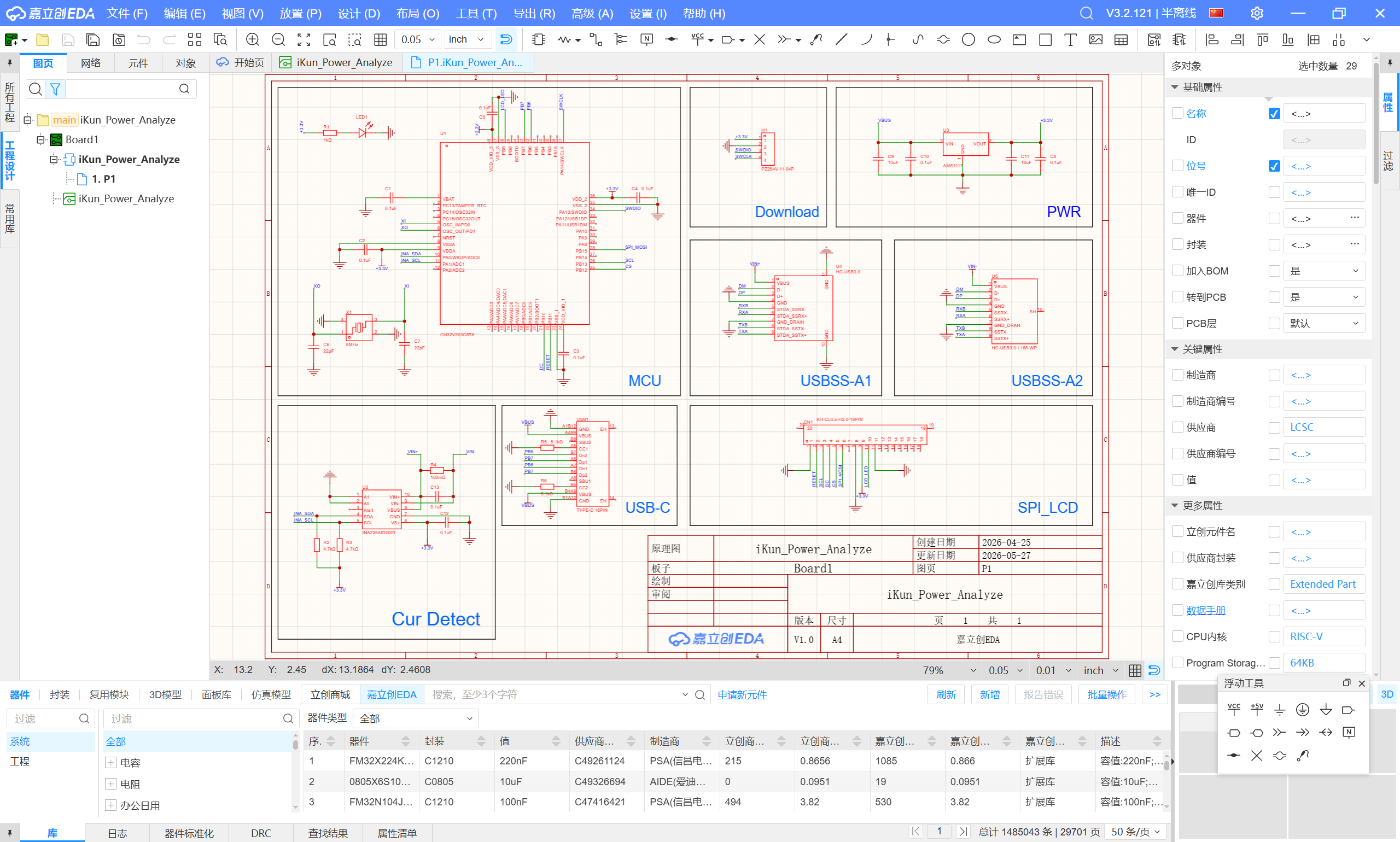
2.1 ikun Power Analyze 的电路设计
沁恒系列的 MCU 外围电路都是属于比较简单的,作者这边仅搭建项目所需的元器件,如下:
1、MCU部分:使用 CH32V203C8T6 作为核心搭建最小系统核心电路;
2、8MHz晶振:CH32V203C8T6 的 HSE 为 8 MHz;
3、USB_type_C:ikun Power Analyze 的 CDC USB 接口;
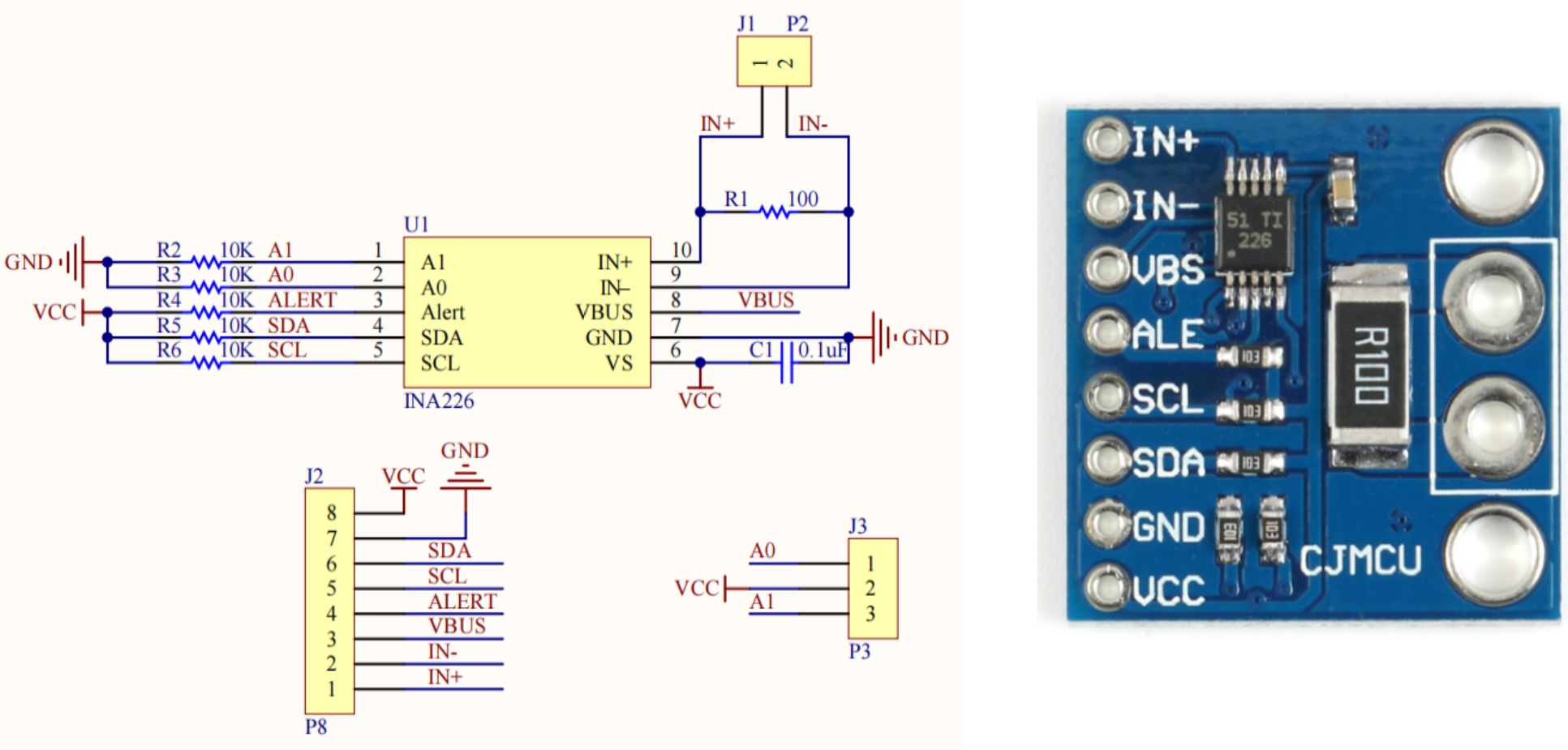
4、电流检测部分:搭建 INA226 的电流检测电路并利用 I2C与其进行通信;
5、USBSS直通部分:USBSS 功率计需要保证被测设备的 USBSS 与 USBHS 均可正常枚举;
6、LCD FPC座:ikun Power Analyze 的电流功率使用 LCD FPC 18p 的软排屏幕;
7、Power 部分:使用 AMS1117 这款 LDO 进行 5v 转 3.3v;
8、LED 与 Download:下载引脚排针与电源指示灯;
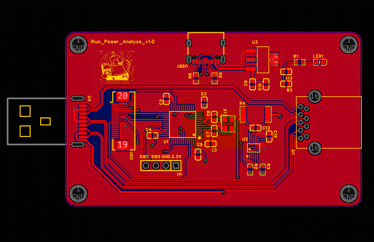
2.2 ikun Power Analyze 的 PCB 设计
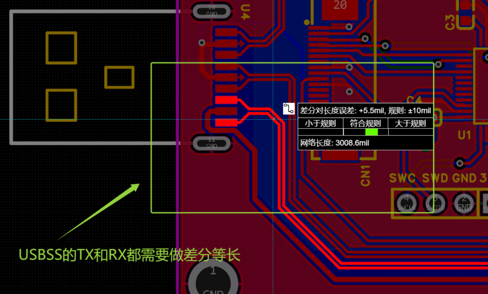
ikun Power Analyze 项目涉及USBSS 与 USBHS 的信号走线,故作者使用 4 Layer 的设计模式,并保证 USBSS 走线尽量不存在过孔操作。其余外围电路设计相关简单易绘制,稍微需要注意项如下:
1、ikun Power Analyze 的直通 USBSS 与 USBFS 走线需要进行差分等长设计;
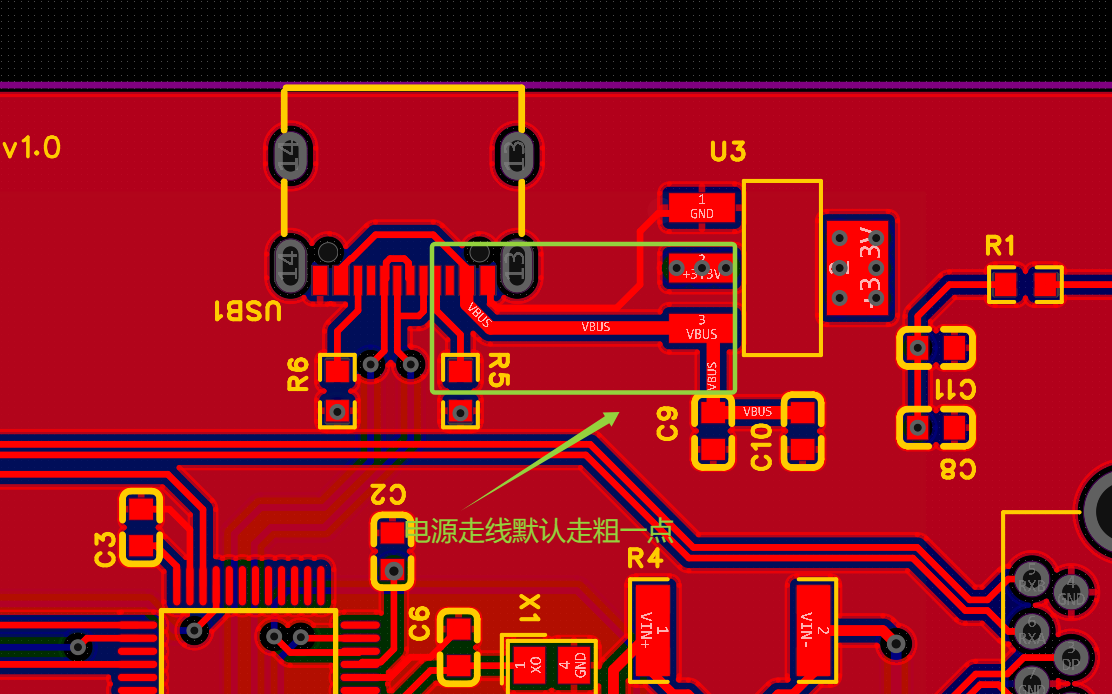
2、AMS1117的电源线稍微加粗:
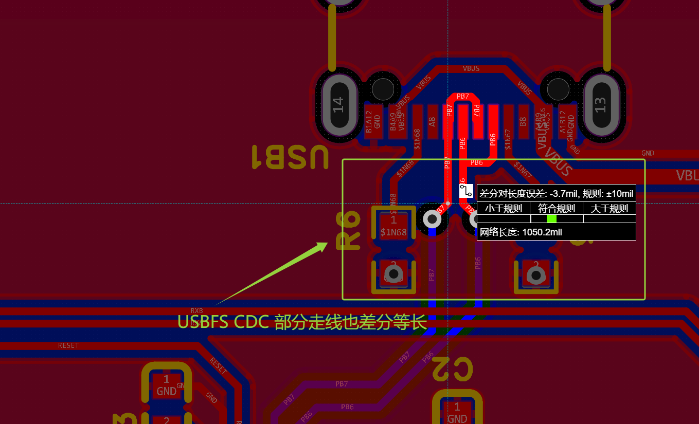
3、与 ikun Power Analyze 软件进行通信的 USBFS CDC 引脚也需做差分等长设计;
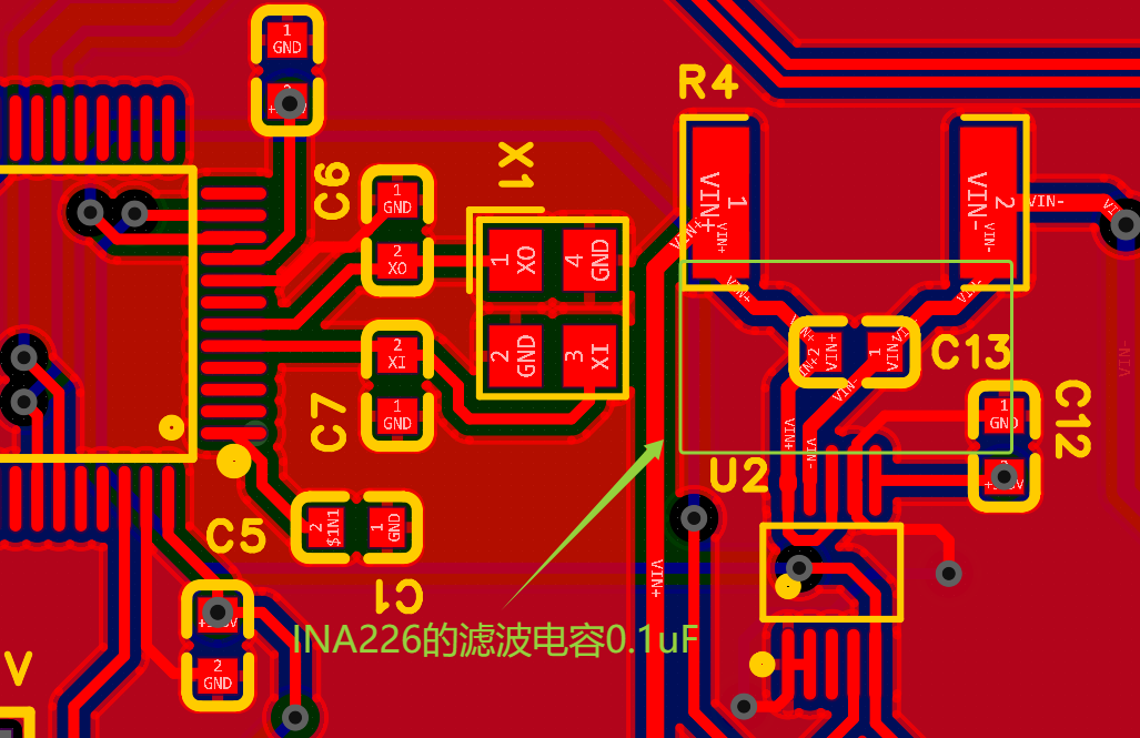
4、INA226 的被测核心电阻 R100 建议推荐补充滤波电容 0.1uF;
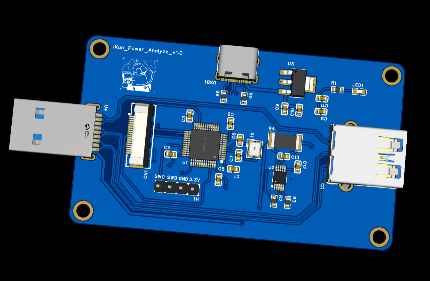
ikun Power Analyze:
三、ikun Power Analyze 的下位机代码
3.1 USBFS 模拟 CDC 代码
作者推荐的 USB 学习博客:USB 2.0 协议专栏之 USB 2.0 概述(一)_usb协议栈-CSDN博客
本项目的 ikun Power Analyze 利用 USB 协议中的 CDC 设备规范进行 USB 数据传输,这部分代码可以直接使用沁恒微电子的 CDC 官方例程即可。作者这边就是在此例程代码上进行修改的,包含:描述符和 CDC 设备枚举中断
usb_desc.c:
#include "usb_desc.h"

/* Device Descriptor */
const uint8_t  MyDevDescr[] =
{
    0x12,       // bLength
    0x01,       // bDescriptorType (Device)
    0x10, 0x01, // bcdUSB 1.10
    0x02,       // bDeviceClass
    0x00,       // bDeviceSubClass
    0x00,       // bDeviceProtocol
    DEF_USBD_UEP0_SIZE,   // bMaxPacketSize0 64
    (uint8_t)DEF_USB_VID, (uint8_t)(DEF_USB_VID >> 8),  // idVendor 0x1A86
    (uint8_t)DEF_USB_PID, (uint8_t)(DEF_USB_PID >> 8),  // idProduct 0xFE0C
    DEF_IC_PRG_VER, 0x00, // bcdDevice 0.01
    0x01,       // iManufacturer (String Index)
    0x02,       // iProduct (String Index)
    0x03,       // iSerialNumber (String Index)
    0x01,       // bNumConfigurations 1
};

/* Configuration Descriptor */
const uint8_t  MyCfgDescr[] =
{
    /* Configure descriptor */
    0x09, 0x02, 0x43, 0x00, 0x02, 0x01, 0x00, 0x80, 0x32,

    /* Interface 0 (CDC) descriptor */
    0x09, 0x04, 0x00, 0x00, 0x01, 0x02, 0x02, 0x01,  0x00,

    /* Functional Descriptors */
    0x05, 0x24, 0x00, 0x10, 0x01,

    /* Length/management descriptor (data class interface 1) */
    0x05, 0x24, 0x01, 0x00, 0x01,
    0x04, 0x24, 0x02, 0x02,
    0x05, 0x24, 0x06, 0x00, 0x01,

    /* Interrupt upload endpoint descriptor */
    0x07, 0x05, 0x81, 0x03, (uint8_t)DEF_USBD_ENDP1_SIZE, (uint8_t)( DEF_USBD_ENDP1_SIZE >> 8 ), 0x01,

    /* Interface 1 (data interface) descriptor */
    0x09, 0x04, 0x01, 0x00, 0x02, 0x0A, 0x00, 0x00, 0x00,

    /* Endpoint descriptor */
    0x07, 0x05, 0x02, 0x02, (uint8_t)DEF_USBD_ENDP2_SIZE, (uint8_t)( DEF_USBD_ENDP2_SIZE >> 8 ), 0x00,

    /* Endpoint descriptor */
    0x07, 0x05, 0x83, 0x02, (uint8_t)DEF_USBD_ENDP3_SIZE, (uint8_t)( DEF_USBD_ENDP3_SIZE >> 8 ), 0x00,
};

/* Language Descriptor */
const uint8_t  MyLangDescr[] =
{
    0x04, 0x03, 0x09, 0x04
};

/* Manufacturer Descriptor */
const uint8_t  MyManuInfo[] =
{
    0x0E, 0x03, 'w', 0, 'c', 0, 'h', 0, '.', 0, 'c', 0, 'n', 0
};

/* Product Information */
const uint8_t  MyProdInfo[] =
{
    0x26, 0x03,
    'i',0, 'K',0, 'u',0, 'n',0, ' ',0,
    'W',0, 'C',0, 'H',0, ' ',0,
    'A',0, 'g',0, 'r',0, ' ',0,
    'D',0, 'e',0, 'b',0, 'u',0, 'g',0
};
/* Serial Number Information */
const uint8_t  MySerNumInfo[] =
{
    0x26, 0x03,
    'i',0, 'K',0, 'u',0, 'n',0, ' ',0,
    'W',0, 'C',0, 'H',0, ' ',0,
    'A',0, 'g',0, 'r',0, ' ',0,
    'D',0, 'e',0, 'b',0, 'u',0, 'g',0
};
ch32v20x_usbfs_device.c:
沁恒系列的 MUC 在进行 USB 设备枚举过程中是利用 void USBFS_IRQHandler 函数进行 Device Descriptors、Configuration Descriptors 和 String Descriptors 的数据交换,作者这边重点讲述一下这部分代码的核心区域:
/********************************** (C) COPYRIGHT *******************************
* File Name : ch32v20x_usbfs_device.c
* Author : WCH
* Version : V1.0.0
* Date : 2022/08/20
* Description : This file provides all the USBFS firmware functions.
*********************************************************************************
* Copyright (c) 2021 Nanjing Qinheng Microelectronics Co., Ltd.
* Attention: This software (modified or not) and binary are used for
* microcontroller manufactured by Nanjing Qinheng Microelectronics.
*******************************************************************************/
#include "ch32v20x_usbfs_device.h"
/*******************************************************************************/
/* Variable Definition */
/* Global */
const uint8_t *pUSBFS_Descr;
/* Setup Request */
volatile uint8_t USBFS_SetupReqCode;
volatile uint8_t USBFS_SetupReqType;
volatile uint16_t USBFS_SetupReqValue;
volatile uint16_t USBFS_SetupReqIndex;
volatile uint16_t USBFS_SetupReqLen;
/* USB Device Status */
volatile uint8_t USBFS_DevConfig;
volatile uint8_t USBFS_DevAddr;
volatile uint8_t USBFS_DevSleepStatus;
volatile uint8_t USBFS_DevEnumStatus;
/* Endpoint Buffer */
__attribute__ ((aligned(4))) uint8_t USBFS_EP0_Buf[ DEF_USBD_UEP0_SIZE ];
__attribute__ ((aligned(4))) uint8_t USBFS_EP1_Buf[ DEF_USBD_ENDP1_SIZE ];
__attribute__ ((aligned(4))) uint8_t USBFS_EP2_Buf[ DEF_USBD_ENDP2_SIZE ];
__attribute__ ((aligned(4))) uint8_t USBFS_EP3_Buf[ DEF_USBD_ENDP3_SIZE ];
/* USB IN Endpoint Busy Flag */
volatile uint8_t USBFS_Endp_Busy[ DEF_UEP_NUM ];
/******************************************************************************/
/* Interrupt Service Routine Declaration*/
void USBFS_IRQHandler(void) __attribute__((interrupt("WCH-Interrupt-fast")));
/*********************************************************************
* @fn USBFS_RCC_Init
*
* @brief Initializes the usbfs clock configuration.
*
* @return none
*/
void USBFS_RCC_Init( void )
{
RCC_ClocksTypeDef RCC_ClocksStatus={0};
RCC_GetClocksFreq(&RCC_ClocksStatus);
if( RCC_ClocksStatus.SYSCLK_Frequency == 144000000 )
{
RCC_USBCLKConfig( RCC_USBCLKSource_PLLCLK_Div3 );
}
else if( RCC_ClocksStatus.SYSCLK_Frequency == 96000000 )
{
RCC_USBCLKConfig( RCC_USBCLKSource_PLLCLK_Div2 );
}
else if( RCC_ClocksStatus.SYSCLK_Frequency == 48000000 )
{
RCC_USBCLKConfig( RCC_USBCLKSource_PLLCLK_Div1 );
}
#if defined(CH32V20x_D8W) || defined(CH32V20x_D8)
else if ( RCC_ClocksStatus.SYSCLK_Frequency == 240000000 && RCC_USB5PRE_JUDGE() == SET )
{
RCC_USBCLKConfig( RCC_USBCLKSource_PLLCLK_Div5 );
}
#endif
RCC_AHBPeriphClockCmd( RCC_AHBPeriph_USBFS, ENABLE );
}
/*********************************************************************
* @fn USBFS_Device_Endp_Init
*
* @brief Initializes USB device endpoints.
*
* @return none
*/
void USBFS_Device_Endp_Init( void )
{
USBFSD->UEP4_1_MOD = USBFS_UEP1_TX_EN;
USBFSD->UEP2_3_MOD = USBFS_UEP2_RX_EN|USBFS_UEP3_TX_EN;
USBFSD->UEP0_DMA = (uint32_t)USBFS_EP0_Buf;
USBFSD->UEP1_DMA = (uint32_t)USBFS_EP1_Buf;
USBFSD->UEP2_DMA = (uint32_t)UART2_Tx_Buf;
USBFSD->UEP3_DMA = (uint32_t)USBFS_EP3_Buf;
USBFSD->UEP0_RX_CTRL = USBFS_UEP_R_RES_ACK;
USBFSD->UEP2_RX_CTRL = USBFS_UEP_R_RES_ACK;
USBFSD->UEP1_TX_LEN = 0;
USBFSD->UEP3_TX_LEN = 0;
USBFSD->UEP0_TX_CTRL = USBFS_UEP_T_RES_NAK;
USBFSD->UEP1_TX_CTRL = USBFS_UEP_T_RES_NAK;
USBFSD->UEP3_TX_CTRL = USBFS_UEP_T_RES_NAK;
/* Clear End-points Busy Status */
for(uint8_t i=0; i<DEF_UEP_NUM; i++ )
{
USBFS_Endp_Busy[ i ] = 0;
}
}
/*********************************************************************
* @fn USBFS_Device_Init
*
* @brief Initializes USB device.
*
* @return none
*/
void USBFS_Device_Init( FunctionalState sta )
{
if( sta )
{
USBFSH->BASE_CTRL = USBFS_UC_RESET_SIE | USBFS_UC_CLR_ALL;
Delay_Us( 10 );
USBFSH->BASE_CTRL = 0x00;
USBFSD->INT_EN = USBFS_UIE_SUSPEND | USBFS_UIE_BUS_RST | USBFS_UIE_TRANSFER;
USBFSD->BASE_CTRL = USBFS_UC_DEV_PU_EN | USBFS_UC_INT_BUSY | USBFS_UC_DMA_EN;
USBFS_Device_Endp_Init( );
USBFSD->UDEV_CTRL = USBFS_UD_PD_DIS | USBFS_UD_PORT_EN;
NVIC_EnableIRQ( USBFS_IRQn );
}
else
{
USBFSH->BASE_CTRL = USBFS_UC_RESET_SIE | USBFS_UC_CLR_ALL;
Delay_Us( 10 );
USBFSD->BASE_CTRL = 0x00;
NVIC_DisableIRQ( USBFS_IRQn );
}
}
/*********************************************************************
* @fn USBFS_Endp_DataUp
*
* @brief USBFS device data upload
*
* @return none
*/
uint8_t USBFS_Endp_DataUp(uint8_t endp, uint8_t *pbuf, uint16_t len, uint8_t mod)
{
uint8_t endp_mode;
uint8_t buf_load_offset;
/* DMA config, endp_ctrl config, endp_len config */
if( (endp>=DEF_UEP1) && (endp<=DEF_UEP7) )
{
if( USBFS_Endp_Busy[ endp ] == 0 )
{
if( (endp == DEF_UEP1) || (endp == DEF_UEP4) )
{
/* endp1/endp4 */
endp_mode = USBFSD_UEP_MOD(0);
if( endp == DEF_UEP1 )
{
endp_mode = (uint8_t)(endp_mode>>4);
}
}
else if( (endp == DEF_UEP2) || (endp == DEF_UEP3) )
{
/* endp2/endp3 */
endp_mode = USBFSD_UEP_MOD(1);
if( endp == DEF_UEP3 )
{
endp_mode = (uint8_t)(endp_mode>>4);
}
}
else if( (endp == DEF_UEP5) || (endp == DEF_UEP6) )
{
/* endp5/endp6 */
endp_mode = USBFSD_UEP_MOD(2);
if( endp == DEF_UEP6 )
{
endp_mode = (uint8_t)(endp_mode>>4);
}
}
else
{
/* endp7 */
endp_mode = USBFSD_UEP_MOD(3);
}
if( endp_mode & USBFSD_UEP_TX_EN )
{
if( endp_mode & USBFSD_UEP_RX_EN )
{
buf_load_offset = 64;
}
else
{
buf_load_offset = 0;
}
if( buf_load_offset == 0 )
{
if( mod == DEF_UEP_DMA_LOAD )
{
/* DMA mode */
USBFSD_UEP_DMA(endp) = (uint16_t)(uint32_t)pbuf;
}
else
{
/* copy mode */
memcpy( USBFSD_UEP_BUF(endp), pbuf, len );
}
}
else
{
memcpy( USBFSD_UEP_BUF(endp)+buf_load_offset, pbuf, len );
}
/* Set end-point busy */
USBFS_Endp_Busy[ endp ] = 0x01;
/* tx length */
USBFSD_UEP_TLEN(endp) = len;
/* response ack */
USBFSD_UEP_CTRL(endp) = (USBFSD_UEP_CTRL(endp) & ~USBFS_UEP_T_RES_MASK) | USBFS_UEP_T_RES_ACK;
}
}
else
{
return 1;
}
}
else
{
return 1;
}
return 0;
}
/*********************************************************************
* @fn USBFS_IRQHandler
*
* @brief This function handles HD-FS exception.
*
* @return none
*/
void USBFS_IRQHandler( void )
{
uint8_t intflag, intst, errflag;
uint16_t len;
uint32_t baudrate;
intflag = USBFSD->INT_FG;
intst = USBFSD->INT_ST;
if( intflag & USBFS_UIF_TRANSFER )
{
switch (intst & USBFS_UIS_TOKEN_MASK)
{
/* data-in stage processing */
case USBFS_UIS_TOKEN_IN:
switch ( intst & ( USBFS_UIS_TOKEN_MASK | USBFS_UIS_ENDP_MASK ) )
{
/* end-point 0 data in interrupt */
case USBFS_UIS_TOKEN_IN | DEF_UEP0:
if( USBFS_SetupReqLen == 0 )
{
USBFSD->UEP0_RX_CTRL = USBFS_UEP_R_TOG | USBFS_UEP_R_RES_ACK;
}
if ( ( USBFS_SetupReqType & USB_REQ_TYP_MASK ) != USB_REQ_TYP_STANDARD )
{
/* Non-standard request endpoint 0 Data upload */
}
else
{
/* Standard request endpoint 0 Data upload */
switch( USBFS_SetupReqCode )
{
case USB_GET_DESCRIPTOR:
len = USBFS_SetupReqLen >= DEF_USBD_UEP0_SIZE ? DEF_USBD_UEP0_SIZE : USBFS_SetupReqLen;
memcpy( USBFS_EP0_Buf, pUSBFS_Descr, len );
USBFS_SetupReqLen -= len;
pUSBFS_Descr += len;
USBFSD->UEP0_TX_LEN = len;
USBFSD->UEP0_TX_CTRL ^= USBFS_UEP_T_TOG;
break;
case USB_SET_ADDRESS:
USBFSD->DEV_ADDR = (USBFSD->DEV_ADDR & USBFS_UDA_GP_BIT) | USBFS_DevAddr;
break;
default:
break;
}
}
break;
/* end-point 1 data in interrupt */
case ( USBFS_UIS_TOKEN_IN | DEF_UEP1 ):
USBFSD->UEP1_TX_CTRL ^= USBFS_UEP_T_TOG;
USBFSD->UEP1_TX_CTRL = (USBFSD->UEP1_TX_CTRL & ~USBFS_UEP_T_RES_MASK) | USBFS_UEP_T_RES_NAK;
USBFS_Endp_Busy[ DEF_UEP1 ] = 0;
break;
/* end-point 3 data in interrupt */
case ( USBFS_UIS_TOKEN_IN | DEF_UEP3 ):
USBFSD->UEP3_TX_CTRL ^= USBFS_UEP_T_TOG;
USBFSD->UEP3_TX_CTRL = (USBFSD->UEP3_TX_CTRL & ~USBFS_UEP_T_RES_MASK) | USBFS_UEP_T_RES_NAK;
USBFS_Endp_Busy[ DEF_UEP3 ] = 0;
Uart.USB_Up_IngFlag = 0x00;
break;
default :
break;
}
break;
/* data-out stage processing */
case USBFS_UIS_TOKEN_OUT:
switch ( intst & ( USBFS_UIS_TOKEN_MASK | USBFS_UIS_ENDP_MASK ) )
{
/* end-point 0 data out interrupt */
case USBFS_UIS_TOKEN_OUT | DEF_UEP0:
len = USBFSD->RX_LEN;
if ( intst & USBFS_UIS_TOG_OK )
{
if ( ( USBFS_SetupReqType & USB_REQ_TYP_MASK ) != USB_REQ_TYP_STANDARD )
{
/* Non-standard request end-point 0 Data download */
USBFS_SetupReqLen = 0;
/* Non-standard request end-point 0 Data download */
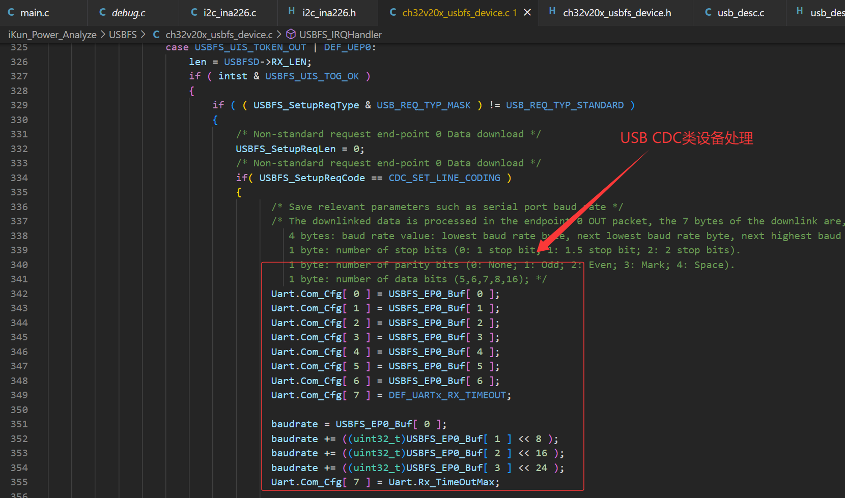
if( USBFS_SetupReqCode == CDC_SET_LINE_CODING )
{
/* Save relevant parameters such as serial port baud rate */
/* The downlinked data is processed in the endpoint 0 OUT packet, the 7 bytes of the downlink are, in order
4 bytes: baud rate value: lowest baud rate byte, next lowest baud rate byte, next highest baud rate byte, highest baud rate byte.
1 byte: number of stop bits (0: 1 stop bit; 1: 1.5 stop bit; 2: 2 stop bits).
1 byte: number of parity bits (0: None; 1: Odd; 2: Even; 3: Mark; 4: Space).
1 byte: number of data bits (5,6,7,8,16); */
Uart.Com_Cfg[ 0 ] = USBFS_EP0_Buf[ 0 ];
Uart.Com_Cfg[ 1 ] = USBFS_EP0_Buf[ 1 ];
Uart.Com_Cfg[ 2 ] = USBFS_EP0_Buf[ 2 ];
Uart.Com_Cfg[ 3 ] = USBFS_EP0_Buf[ 3 ];
Uart.Com_Cfg[ 4 ] = USBFS_EP0_Buf[ 4 ];
Uart.Com_Cfg[ 5 ] = USBFS_EP0_Buf[ 5 ];
Uart.Com_Cfg[ 6 ] = USBFS_EP0_Buf[ 6 ];
Uart.Com_Cfg[ 7 ] = DEF_UARTx_RX_TIMEOUT;
baudrate = USBFS_EP0_Buf[ 0 ];
baudrate += ((uint32_t)USBFS_EP0_Buf[ 1 ] << 8 );
baudrate += ((uint32_t)USBFS_EP0_Buf[ 2 ] << 16 );
baudrate += ((uint32_t)USBFS_EP0_Buf[ 3 ] << 24 );
Uart.Com_Cfg[ 7 ] = Uart.Rx_TimeOutMax;
UART2_USB_Init( );
}
}
else
{
/* Standard request end-point 0 Data download */
/* Add your code here */
}
if( USBFS_SetupReqLen == 0 )
{
USBFSD->UEP0_TX_LEN = 0;
USBFSD->UEP0_TX_CTRL = USBFS_UEP_T_TOG | USBFS_UEP_T_RES_ACK;
}
}
break;
/* end-point 1 data out interrupt */
case USBFS_UIS_TOKEN_OUT | DEF_UEP2:
USBFSD->UEP2_RX_CTRL ^= USBFS_UEP_R_TOG;
Uart.Tx_PackLen[ Uart.Tx_LoadNum ] = USBFSD->RX_LEN;
Uart.Tx_LoadNum++;
USBFSD->UEP2_DMA = (uint32_t)(uint8_t *)&UART2_Tx_Buf[ ( Uart.Tx_LoadNum * DEF_USB_FS_PACK_LEN ) ];
if( Uart.Tx_LoadNum >= DEF_UARTx_TX_BUF_NUM_MAX )
{
Uart.Tx_LoadNum = 0x00;
USBFSD->UEP2_DMA = (uint32_t)(uint8_t *)&UART2_Tx_Buf[ 0 ];
}
Uart.Tx_RemainNum++;
if( Uart.Tx_RemainNum >= ( DEF_UARTx_TX_BUF_NUM_MAX - 2 ) )
{
USBFSD->UEP2_RX_CTRL &= ~USBFS_UEP_R_RES_MASK;
USBFSD->UEP2_RX_CTRL |= USBFS_UEP_R_RES_NAK;
Uart.USB_Down_StopFlag = 0x01;
}
break;
default:
break;
}
break;
/* Setup stage processing */
case USBFS_UIS_TOKEN_SETUP:
USBFSD->UEP0_TX_CTRL = USBFS_UEP_T_TOG|USBFS_UEP_T_RES_NAK;
USBFSD->UEP0_RX_CTRL = USBFS_UEP_R_TOG|USBFS_UEP_R_RES_NAK;
/* Store All Setup Values */
USBFS_SetupReqType = pUSBFS_SetupReqPak->bRequestType;
USBFS_SetupReqCode = pUSBFS_SetupReqPak->bRequest;
USBFS_SetupReqLen = pUSBFS_SetupReqPak->wLength;
USBFS_SetupReqValue = pUSBFS_SetupReqPak->wValue;
USBFS_SetupReqIndex = pUSBFS_SetupReqPak->wIndex;
len = 0;
errflag = 0;
if ( ( USBFS_SetupReqType & USB_REQ_TYP_MASK ) != USB_REQ_TYP_STANDARD )
{
/* usb non-standard request processing */
if( USBFS_SetupReqType & USB_REQ_TYP_CLASS )
{
/* Class requests */
switch( USBFS_SetupReqCode )
{
case CDC_GET_LINE_CODING:
pUSBFS_Descr = (uint8_t *)&Uart.Com_Cfg[ 0 ];
len = 7;
break;
case CDC_SET_LINE_CODING:
break;
case CDC_SET_LINE_CTLSTE:
break;
case CDC_SEND_BREAK:
break;
default:
errflag = 0xff;
break;
}
}
else if( USBFS_SetupReqType & USB_REQ_TYP_VENDOR )
{
/* Manufacturer request */
}
else
{
errflag = 0xFF;
}
/* Copy Descriptors to Endp0 DMA buffer */
len = (USBFS_SetupReqLen >= DEF_USBD_UEP0_SIZE) ? DEF_USBD_UEP0_SIZE : USBFS_SetupReqLen;
memcpy( USBFS_EP0_Buf, pUSBFS_Descr, len );
pUSBFS_Descr += len;
}
else
{
/* usb standard request processing */
switch( USBFS_SetupReqCode )
{
/* get device/configuration/string/report/... descriptors */
case USB_GET_DESCRIPTOR:
switch( (uint8_t)( USBFS_SetupReqValue >> 8 ) )
{
/* get usb device descriptor */
case USB_DESCR_TYP_DEVICE:
pUSBFS_Descr = MyDevDescr;
len = DEF_USBD_DEVICE_DESC_LEN;
break;
/* get usb configuration descriptor */
case USB_DESCR_TYP_CONFIG:
pUSBFS_Descr = MyCfgDescr;
len = DEF_USBD_CONFIG_DESC_LEN;
break;
/* get usb string descriptor */
case USB_DESCR_TYP_STRING:
switch( (uint8_t)( USBFS_SetupReqValue & 0xFF ) )
{
/* Descriptor 0, Language descriptor */
case DEF_STRING_DESC_LANG:
pUSBFS_Descr = MyLangDescr;
len = DEF_USBD_LANG_DESC_LEN;
break;
/* Descriptor 1, Manufacturers String descriptor */
case DEF_STRING_DESC_MANU:
pUSBFS_Descr = MyManuInfo;
len = DEF_USBD_MANU_DESC_LEN;
break;
/* Descriptor 2, Product String descriptor */
case DEF_STRING_DESC_PROD:
pUSBFS_Descr = MyProdInfo;
len = DEF_USBD_PROD_DESC_LEN;
break;
/* Descriptor 3, Serial-number String descriptor */
case DEF_STRING_DESC_SERN:
pUSBFS_Descr = MySerNumInfo;
len = DEF_USBD_SN_DESC_LEN;
break;
default:
errflag = 0xFF;
break;
}
break;
default :
errflag = 0xFF;
break;
}
/* Copy Descriptors to Endp0 DMA buffer */
if( USBFS_SetupReqLen>len )
{
USBFS_SetupReqLen = len;
}
len = (USBFS_SetupReqLen >= DEF_USBD_UEP0_SIZE) ? DEF_USBD_UEP0_SIZE : USBFS_SetupReqLen;
memcpy( USBFS_EP0_Buf, pUSBFS_Descr, len );
pUSBFS_Descr += len;
break;
/* Set usb address */
case USB_SET_ADDRESS:
USBFS_DevAddr = (uint8_t)( USBFS_SetupReqValue & 0xFF );
break;
/* Get usb configuration now set */
case USB_GET_CONFIGURATION:
USBFS_EP0_Buf[0] = USBFS_DevConfig;
if ( USBFS_SetupReqLen > 1 )
{
USBFS_SetupReqLen = 1;
}
break;
/* Set usb configuration to use */
case USB_SET_CONFIGURATION:
USBFS_DevConfig = (uint8_t)( USBFS_SetupReqValue & 0xFF );
USBFS_DevEnumStatus = 0x01;
break;
/* Clear or disable one usb feature */
case USB_CLEAR_FEATURE:
if ( ( USBFS_SetupReqType & USB_REQ_RECIP_MASK ) == USB_REQ_RECIP_DEVICE )
{
/* clear one device feature */
if( (uint8_t)( USBFS_SetupReqValue & 0xFF ) == USB_REQ_FEAT_REMOTE_WAKEUP )
{
/* clear usb sleep status, device not prepare to sleep */
USBFS_DevSleepStatus &= ~0x01;
}
}
else if( ( USBFS_SetupReqType & USB_REQ_RECIP_MASK ) == USB_REQ_RECIP_ENDP )
{
/* Clear End-point Feature */
if( (uint8_t)( USBFS_SetupReqValue & 0xFF ) == USB_REQ_FEAT_ENDP_HALT )
{
switch( (uint8_t)( USBFS_SetupReqIndex & 0xFF ) )
{
case ( DEF_UEP_IN | DEF_UEP1 ):
/* Set End-point 1 IN NAK */
USBFSD->UEP1_TX_CTRL = USBFS_UEP_T_RES_NAK;
break;
case ( DEF_UEP_OUT | DEF_UEP2 ):
/* Set End-point 2 OUT ACK */
USBFSD->UEP2_RX_CTRL = USBFS_UEP_R_RES_ACK;
break;
case ( DEF_UEP_IN | DEF_UEP3 ):
/* Set End-point 3 IN NAK */
USBFSD->UEP3_TX_CTRL = USBFS_UEP_T_RES_NAK;
break;
default:
errflag = 0xFF;
break;
}
}
else
{
errflag = 0xFF;
}
}
else
{
errflag = 0xFF;
}
break;
/* set or enable one usb feature */
case USB_SET_FEATURE:
if( ( USBFS_SetupReqType & USB_REQ_RECIP_MASK ) == USB_REQ_RECIP_DEVICE )
{
/* Set Device Feature */
if( (uint8_t)( USBFS_SetupReqValue & 0xFF ) == USB_REQ_FEAT_REMOTE_WAKEUP )
{
if( MyCfgDescr[ 7 ] & 0x20 )
{
/* Set Wake-up flag, device prepare to sleep */
USBFS_DevSleepStatus |= 0x01;
}
else
{
errflag = 0xFF;
}
}
else
{
errflag = 0xFF;
}
}
else if( ( USBFS_SetupReqType & USB_REQ_RECIP_MASK ) == USB_REQ_RECIP_ENDP )
{
/* Set End-point Feature */
if( (uint8_t)( USBFS_SetupReqValue & 0xFF ) == USB_REQ_FEAT_ENDP_HALT )
{
/* Set end-points status stall */
switch( (uint8_t)( USBFS_SetupReqIndex & 0xFF ) )
{
case ( DEF_UEP_IN | DEF_UEP1 ):
/* Set End-point 1 IN STALL */
USBFSD->UEP1_TX_CTRL = ( USBFSD->UEP1_TX_CTRL & ~USBFS_UEP_T_RES_MASK ) | USBFS_UEP_T_RES_STALL;
break;
case ( DEF_UEP_OUT | DEF_UEP2 ):
/* Set End-point 2 OUT STALL */
USBFSD->UEP2_RX_CTRL = ( USBFSD->UEP2_RX_CTRL & ~USBFS_UEP_R_RES_MASK ) | USBFS_UEP_R_RES_STALL;
break;
case ( DEF_UEP_IN | DEF_UEP3 ):
/* Set End-point 3 IN STALL */
USBFSD->UEP3_TX_CTRL = ( USBFSD->UEP3_TX_CTRL & ~USBFS_UEP_T_RES_MASK ) | USBFS_UEP_T_RES_STALL;
break;
default:
errflag = 0xFF;
break;
}
}
else
{
errflag = 0xFF;
}
}
else
{
errflag = 0xFF;
}
break;
/* This request allows the host to select another setting for the specified interface */
case USB_GET_INTERFACE:
USBFS_EP0_Buf[0] = 0x00;
if ( USBFS_SetupReqLen > 1 )
{
USBFS_SetupReqLen = 1;
}
break;
case USB_SET_INTERFACE:
break;
/* host get status of specified device/interface/end-points */
case USB_GET_STATUS:
USBFS_EP0_Buf[ 0 ] = 0x00;
USBFS_EP0_Buf[ 1 ] = 0x00;
if ( ( USBFS_SetupReqType & USB_REQ_RECIP_MASK ) == USB_REQ_RECIP_DEVICE )
{
if( USBFS_DevSleepStatus & 0x01 )
{
USBFS_EP0_Buf[ 0 ] = 0x02;
}
}
else if( ( USBFS_SetupReqType & USB_REQ_RECIP_MASK ) == USB_REQ_RECIP_ENDP )
{
switch( (uint8_t)( USBFS_SetupReqIndex & 0xFF ) )
{
case ( DEF_UEP_IN | DEF_UEP1 ):
if( ( (USBFSD->UEP1_TX_CTRL) & USBFS_UEP_T_RES_MASK ) == USBFS_UEP_T_RES_STALL )
{
USBFS_EP0_Buf[ 0 ] = 0x01;
}
break;
case ( DEF_UEP_OUT | DEF_UEP2 ):
if( ( (USBFSD->UEP2_RX_CTRL) & USBFS_UEP_R_RES_MASK ) == USBFS_UEP_R_RES_STALL )
{
USBFS_EP0_Buf[ 0 ] = 0x01;
}
break;
case ( DEF_UEP_IN | DEF_UEP3 ):
if( ( (USBFSD->UEP3_TX_CTRL) & USBFS_UEP_T_RES_MASK ) == USBFS_UEP_T_RES_STALL )
{
USBFS_EP0_Buf[ 0 ] = 0x01;
}
break;
default:
errflag = 0xFF;
break;
}
}
else
{
errflag = 0xFF;
}
if( USBFS_SetupReqLen > 2 )
{
USBFS_SetupReqLen = 2;
}
break;
default:
errflag = 0xFF;
break;
}
}
/* errflag = 0xFF means a request not support or some errors occurred, else correct */
if( errflag == 0xff)
{
/* if one request not support, return stall */
USBFSD->UEP0_TX_CTRL = USBFS_UEP_T_TOG|USBFS_UEP_T_RES_STALL;
USBFSD->UEP0_RX_CTRL = USBFS_UEP_R_TOG|USBFS_UEP_R_RES_STALL;
}
else
{
/* end-point 0 data Tx/Rx */
if( USBFS_SetupReqType & DEF_UEP_IN )
{
/* tx */
len = (USBFS_SetupReqLen>DEF_USBD_UEP0_SIZE) ? DEF_USBD_UEP0_SIZE : USBFS_SetupReqLen;
USBFS_SetupReqLen -= len;
USBFSD->UEP0_TX_LEN = len;
USBFSD->UEP0_TX_CTRL = USBFS_UEP_T_TOG|USBFS_UEP_T_RES_ACK;
}
else
{
/* rx */
if( USBFS_SetupReqLen == 0 )
{
USBFSD->UEP0_TX_LEN = 0;
USBFSD->UEP0_TX_CTRL = USBFS_UEP_T_TOG|USBFS_UEP_T_RES_ACK;
}
else
{
USBFSD->UEP0_RX_CTRL = USBFS_UEP_R_TOG|USBFS_UEP_R_RES_ACK;
}
}
}
break;
default :
break;
}
USBFSD->INT_FG = USBFS_UIF_TRANSFER;
}
else if( intflag & USBFS_UIF_BUS_RST )
{
/* usb reset interrupt processing */
USBFS_DevConfig = 0;
USBFS_DevAddr = 0;
USBFS_DevSleepStatus = 0;
USBFS_DevEnumStatus = 0;
USBFSD->DEV_ADDR = 0;
USBFS_Device_Endp_Init( );
UART2_ParaInit( 1 );
USBFSD->INT_FG = USBFS_UIF_BUS_RST;
}
else if( intflag & USBFS_UIF_SUSPEND )
{
USBFSD->INT_FG = USBFS_UIF_SUSPEND;
Delay_Us(10);
/* usb suspend interrupt processing */
if ( USBFSD->MIS_ST & USBFS_UMS_SUSPEND )
{
USBFS_DevSleepStatus |= 0x02;
if( USBFS_DevSleepStatus == 0x03 )
{
/* Handling usb sleep here */
}
}
else
{
USBFS_DevSleepStatus &= ~0x02;
}
}
else
{
/* other interrupts */
USBFSD->INT_FG = intflag;
}
}
/*********************************************************************
* @fn USBFS_Send_Resume
*
* @brief USBFS device sends wake-up signal to host
*
* @return none
*/
void USBFS_Send_Resume(void)
{
}
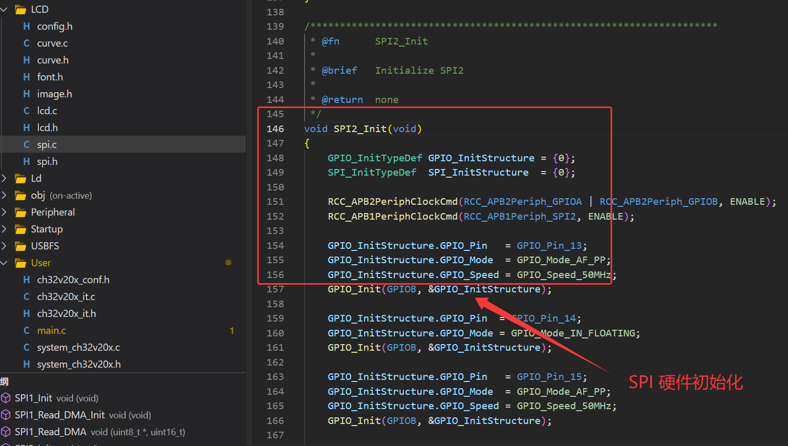
3.2 SPI 驱动 2.4 寸 TFT_LCD 显示
作者推荐的 2.4寸 TFT_LCD 学习博客:【强烈推荐】基于STM32的TFT-LCD各种显示实现(内容详尽含代码)_tftlcd屏幕 dc引脚可以和其他引脚共用吗-CSDN博客
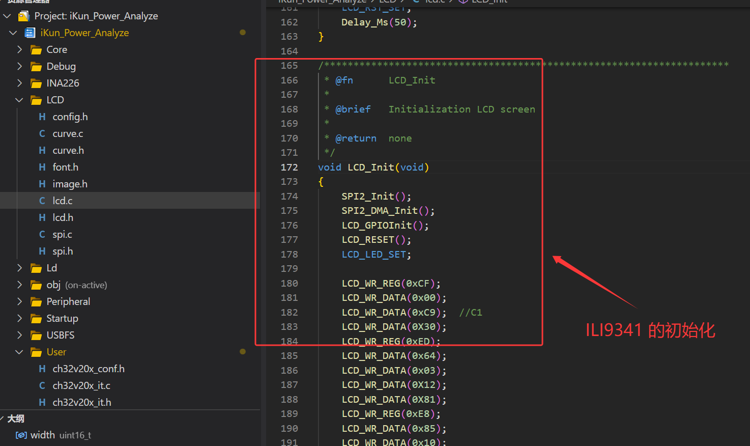
作者 ikun Power Analyze 使用的是 2.4 寸 TFT_LCD(320*240),LCD 的驱动芯片为 ILI9341,各位读者朋友可以使用自己手上的 LCD 即可。且作者额外使用嘉立创 EDA 绘制了 2.4寸 LCD 放置板,作者也在开源文件中进行了提供。2.4 寸 TFT_LCD(ILI9341)属于使用 SPI 进行驱动,作者使用 MCU 的硬件 SPI 与其进行通信,这部分的代码都属于传统的 LCD 驱动类代码。考虑到博客的篇幅受限,这部分的内容推荐读者朋友们参考博主之前的博客。
3.2.1 TFT_LCD 图像与数字显示
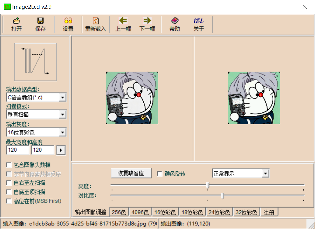
1、TFT_LCD 图像显示:
使用 Img2Lcd 软件进行图像取模操作,Img2Lcd 使用方法很简单,对于 RGB565 的真彩选择:16 位真彩,其余选择如下图(额外说明:取模方式直接与代码程序的图像显示结果挂钩,如果读者朋友的图像显示异常,请考虑是否代码与图像取模一致):
/**
 * @brief Display 99*100 RGB565 bitmap on specified LCD area
 * @param p Pointer to RGB565 image data buffer (little-endian format)
 */
void Showimage(const unsigned char *p)
{
    LCD_SetWindows(110, 70, 208, 169);
    LCD_DC_SET;
    for (int y = 0; y < 100; y++)
    {
        for (int x = 0; x < 99; x++)
        {
            int index = (y * 99 + x) * 2;
            uint16_t color = p[index] | (p[index+1] << 8);
            Lcd_WriteData_16Bit(color);
        }
    }
    LCD_CS_SET;
}
ikun Power Analyze 的 U、I、P 也使用如上方的 API 函数进行绘制即可(需要稍微修改一下函数里的部分数值即可):
/**
 * @brief Display 40*39 RGB565 bitmap (Position U)
 * @param p Pointer to RGB565 image data buffer
 */
void Showimage_40_U(const unsigned char *p)
{
    LCD_SetWindows(10, 10, 49, 48);
    LCD_DC_SET;
    for (int y = 0; y < 39; y++)
    {
        for (int x = 0; x < 40; x++)
        {
            int index = (y * 40 + x) * 2;
            uint16_t color = p[index] | (p[index+1] << 8);
            Lcd_WriteData_16Bit(color);
        }
    }
    LCD_CS_SET;
}

/**
 * @brief Display 40*39 RGB565 bitmap (Position I)
 * @param p Pointer to RGB565 image data buffer
 */
void Showimage_40_I(const unsigned char *p)
{
    LCD_SetWindows(10, 60, 49, 98);
    LCD_DC_SET;
    for (int y = 0; y < 39; y++)
    {
        for (int x = 0; x < 40; x++)
        {
            int index = (y * 40 + x) * 2;
            uint16_t color = p[index] | (p[index+1] << 8);
            Lcd_WriteData_16Bit(color);
        }
    }
    LCD_CS_SET;
}

/**
 * @brief Display 40*39 RGB565 bitmap (Position P)
 * @param p Pointer to RGB565 image data buffer
 */
void Showimage_40_P(const unsigned char *p)
{
    LCD_SetWindows(10, 110, 49, 148);
    LCD_DC_SET;
    for (int y = 0; y < 39; y++) {
        for (int x = 0; x < 40; x++) {
            int index = (y * 40 + x) * 2;
            uint16_t color = p[index] | (p[index+1] << 8);
            Lcd_WriteData_16Bit(color);
        }
    }
    LCD_CS_SET;
}

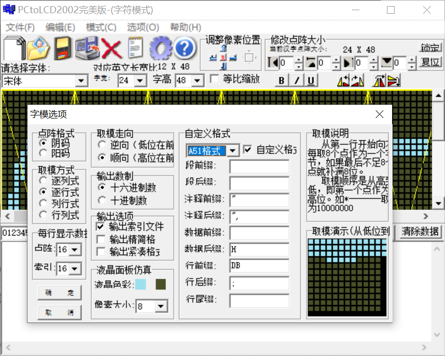
2、TFT_LCD 数字显示:
2.4 寸 TFT_LCD 的数字显示则使用如下的 API 函数调用字库的字模即可(作者补充说明:这个地方的取模与图像一样,如果取模方式与字体显示的编写代码未保持一致,可能导致最终的数字显示异常):
/**
 * @brief Display a float number using 24x48 font
 * @param x       Start X coordinate
 * @param y       Start Y coordinate
 * @param num     Float number to display
 * @param dec     Number of decimal places (0-4)
 * @param color   Text color
 * @param spacing Character spacing in pixels (recommended 3-5)
 */
void LCD_ShowBigFloat_24x48(uint16_t x, uint16_t y, float num, uint8_t dec, uint16_t color, uint8_t spacing) {
    char buf[20] = {0};

    if (num < 0) num = 0.0f;

    if (dec == 0) {
        sprintf(buf, "%d", (int)num);
    } else if (dec == 1) {
        sprintf(buf, "%.1f", num);
    } else if (dec == 2) {
        sprintf(buf, "%.2f", num);
    } else if (dec == 3) {
        sprintf(buf, "%.3f", num);
    } else {
        sprintf(buf, "%.4f", num);
    }

    uint8_t len = 0;
    while (buf[len]) len++;

    uint16_t total_w = len * 24 + (len - 1) * spacing;
    LCD_Fill_Rect_Fast(x, y, total_w, 48, LCD_BLACK);

    uint16_t curX = x;
    for (uint8_t i = 0; i < len; i++) {
        LCD_DrawBigChar_24x48(curX, y, buf[i], color);
        curX += 24 + spacing;
    }
}
3.2.2 TFT_LCD 电流曲线绘制
作者的 ikun Power Analyze 额外的在 TFT_LCD 部分增加了电流曲线的绘制功能,方便读者朋友们在日常使用 USBSS 功率计的时候开源更加灵敏与直观的感受到当前被测负载的电流变化情况!作者使用的 Current 电流曲线绘制的代码核心逻辑为:结构体管理绘图区域 + 环形线性数据缓存 + 坐标映射 + 网格绘制 + 高速填充刷新,纯嵌入式裸机实现,适配传统 8/32 位 MCU。
curve.c:
/*********************************************************************
 * File Name          : curve.c
 * Author             : 混分巨兽龙某某
 * Version            : V1.0.0
 * Date               : 2026/4/29
 * Description        : Curve drawing driver for LCD, implement real-time waveform display
*******************************************************************************/

#include "curve.h"
#include <stdlib.h>
#include <string.h>

/**
 * @brief   Fast fill rectangle by LCD burst write
 * @param   x:      Rectangle start X coordinate
 * @param   y:      Rectangle start Y coordinate
 * @param   w:      Rectangle width
 * @param   h:      Rectangle height
 * @param   color:  Fill color (RGB565)
 * @retval  None
 */
static void FillRectFast(uint16_t x, uint16_t y, uint16_t w, uint16_t h, uint16_t color) {
    LCD_SetWindows(x, y, x + w - 1, y + h - 1);
    LCD_CS_CLR;
    LCD_DC_SET;
    for (uint32_t i = 0; i < (uint32_t)w * h; i++) {
        SPI2_Write(color >> 8);
        SPI2_Write(color & 0xFF);
    }
    LCD_CS_SET;
    LCD_SetWindows(0, 0, LCD_H - 1, LCD_W - 1);
}

/**
 * @brief   Draw coordinate grid for curve area
 * @param   area:   Pointer to curve display area structure
 * @retval  None
 * @note    Draw left border, bottom border, zero line and vertical dashed grid
 */
static void DrawGrid(CurveArea *area) {
    if (!area->draw_grid) return;
    uint16_t x0 = area->x, y0 = area->y, w = area->w, h = area->h;

    /* Draw bottom border */
    for (uint16_t i = 0; i < w; i++) {
        LCD_DrawPoint(x0 + i, y0 + h - 1, area->grid_color);
    }
    /* Draw left border */
    for (uint16_t j = 0; j < h; j++) {
        LCD_DrawPoint(x0, y0 + j, area->grid_color);
    }

    /* Draw horizontal zero reference line */
    if (area->y_min <= 0 && area->y_max >= 0) {
        uint16_t yzero = y0 + (uint16_t)((long)(h - 1) * (0 - area->y_min) / (area->y_max - area->y_min));
        if (yzero != y0) {
            for (uint16_t i = 0; i < w; i++) {
                LCD_DrawPoint(x0 + i, yzero, area->grid_color);
            }
        }
    }

    /* Draw vertical dashed grid line (interval 20 pixels) */
    for (uint16_t x = x0 + 20; x < x0 + w - 1; x += 20) {
        for (uint16_t y = y0 + 1; y < y0 + h - 1; y += 5) {
            LCD_DrawPoint(x, y, area->grid_color);
        }
    }
}

/**
 * @brief   Convert raw data value to LCD Y pixel coordinate
 * @param   area:   Pointer to curve display area structure
 * @param   data:   Raw input data
 * @retval  Calculated Y offset inside curve area
 * @note    Limit data in [y_min, y_max], adapt LCD top-down coordinate system
 */
static uint16_t DataToY(CurveArea *area, int16_t data) {
    /* Clamp data to valid range */
    if (data < area->y_min) data = area->y_min;
    if (data > area->y_max) data = area->y_max;

    /* Convert data to Y pixel (LCD Y increases downward) */
    uint16_t y_pixel = area->h -
        ((int32_t)(data - area->y_min) * area->h) / (area->y_max - area->y_min);

    return y_pixel;
}

/**
 * @brief   Initialize curve display area and buffer
 * @param   area:       Pointer to CurveArea struct
 * @param   x:          Area start X
 * @param   y:          Area start Y
 * @param   w:          Area width
 * @param   h:          Area height
 * @param   y_min:      Minimum Y data range
 * @param   y_max:      Maximum Y data range
 * @param   line_color: Curve line color
 * @param   bg_color:   Background color
 * @retval  None
 */
void Curve_Init(CurveArea *area, uint16_t x, uint16_t y, uint16_t w, uint16_t h,
                int16_t y_min, int16_t y_max, uint16_t line_color, uint16_t bg_color) {
    area->x = x; area->y = y; area->w = w; area->h = h;
    area->y_min = y_min; area->y_max = y_max;
    area->line_color = line_color; area->bg_color = bg_color;
    area->grid_color = LCD_GRAY;
    area->draw_grid = 1;
    area->buf = (uint16_t*)malloc(w * sizeof(uint16_t));
    area->count = 0;  /* Reset data point counter */

    if (area->buf) {
        for (uint16_t i = 0; i < w; i++) {
            area->buf[i] = 0xFFFF;
        }
    }

    FillRectFast(x, y, w, h, bg_color);
    DrawGrid(area);
}

/**
 * @brief   Add one new data point and draw curve line
 * @param   area:   Pointer to CurveArea struct
 * @param   data:   New input data value
 * @retval  None
 * @note    Auto clear & restart when buffer is full
 */
void Curve_AddPoint(CurveArea *area, int16_t data) {
    if (!area->buf) return;

    uint16_t new_y = DataToY(area, data);

    if (area->count < area->w) {
        uint16_t current_x = area->x + area->count;
        area->buf[area->count] = new_y;

        /* Draw line between current point and previous point */
        if (area->count > 0 && area->buf[area->count - 1] != 0xFFFF) {
            LCD_DrawLine(current_x - 1, area->y + area->buf[area->count - 1],
                         current_x, area->y + new_y,
                         area->line_color);
        }

        area->count++;
    } else {
        /* Buffer full, clear all and restart drawing */
        Curve_Clear(area);
        area->buf[0] = new_y;
        area->count = 1;
    }
}

/**
 * @brief   Clear curve area and reset data buffer
 * @param   area:   Pointer to CurveArea struct
 * @retval  None
 */
void Curve_Clear(CurveArea *area) {
    if (!area->buf) return;
    for (uint16_t i = 0; i < area->w; i++) {
        area->buf[i] = 0xFFFF;
    }
    area->count = 0;
    FillRectFast(area->x, area->y, area->w, area->h, area->bg_color);
    DrawGrid(area);
}

/**
 * @brief   Deinitialize curve module, release dynamic memory
 * @param   area:   Pointer to CurveArea struct
 * @retval  None
 */
void Curve_Deinit(CurveArea *area) {
    if (area->buf) {
        free(area->buf);
        area->buf = NULL;
    }
}
3.3 INA226 驱动代码
3.3.1 INA226 的核心寄存器解读
1、配置寄存器 0x00
INA226 配置寄存器 0x00 设置控制设备的工作模式。该寄存器控制分流和总线电压测量以及所用的平均模式的转换时间设置。
2、分流电压寄存器 0x01
分流电压寄存器 0x01 用于存储当前的分流电压读数 Vshunt。负数采用二进制补码格式表示。生成一个负数的补码方法是:对其绝对值的二进制数取反,然后加 1。如果最高有效位(MSB)为 '1',则表示这是一个负数。最小分辨率(Vshunt _LSB)为 2.5uV。
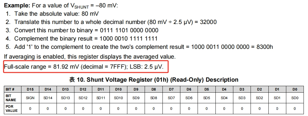
注意分流电压最大81.92mV,而该模块的采样电阻是0.1R,故最大电流为 81.92mV / 0.1R = 819.2mA;分流电压计算:Vshunt = 寄存器值 * Vshunt _LSB(2.5uV)
3、总线电压寄存器 0x02
总线电压寄存器 0x02 用于存储最近一次的总线电压读数 Vbus。如果启用了平均功能,则该寄存器显示的是平均后的数值。满量程范围为 40.96V(对应 7FFF);最小分辨率(Vbus_LSB)为 1.25 mV。
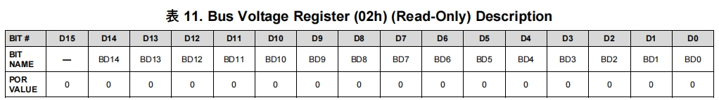
总线电压计算:Vbus = 寄存器值 * Vbus_LSB(1.25 mV )
4、功率寄存器 0x03
功率寄存器 0x03 用于存储功率读数 Power ,如果启用了平均功能,该寄存器将显示平均值。功率寄存器的最低有效位(LSB)在内部被设定为等于 Current_LSB 所设定值的 25 倍 。功率寄存器通过将电流寄存器的十进制值与总线电压寄存器的十进制值相乘来记录以瓦特(Watts)为单位的功率。
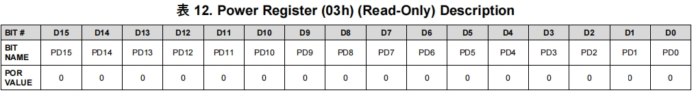
Power 计算: Power = 寄存器值 * Power_ LSB
由手册可知 Power_LSB(功率最小分辨率) = Current_LSB(电流最小分辨率) * 25
Current_LSB 手册给出了计算公式,如下
Current_LSB = 最大电流 / 2^15 = 819.2mA / 2^15 = 0.025mA
而手册内有一段提示:While this value yields the highest resolution, it is common to select a value for the Current_LSB to the nearest round number above this value to simplify the conversion of the Current Register (04h) and Power Register (03h) to amperes and watts respectively
译文:虽然这个值可以提供最高的分辨率,但通常会选择一个略高于该值的整数作为 Current_LSB,以简化将电流寄存器(04h)和功率寄存器(03h)转换为安培(Amperes)和瓦特(Watts)的过程
也就是可以自己根据公式计算出的结果,选择一个合适的 Current_LSB 值,便于计算,这里公式得出的 Current_LSB = 0.025mA,本文重新选择为 0.05mA,之所以选择 0.05 也为了便于后续 CAL (基准值) 的计算,详见寄存器 0x05 说明
故 Power_LSB = 0.05mA * 25 = 1.25mW
功率计算: Power = 寄存器值 * Power_ LSB(1.25mW)
5、电流寄存器 0x04
电流寄存器 0x04 用于存储电流读数 Current,如果启用了平均功能,该寄存器将显示平均值。电流寄存器的值是通过将分流电压寄存器中的十进制值与校准寄存器中的十进制值相乘来计算的
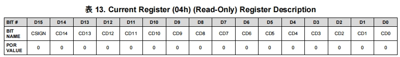
电流值 = 寄存器值 * Current_LSB(0.05mA) (Current_LSB 的计算在上文功率寄存器小节已经给出)
3.3.2 INA226 的代码编写
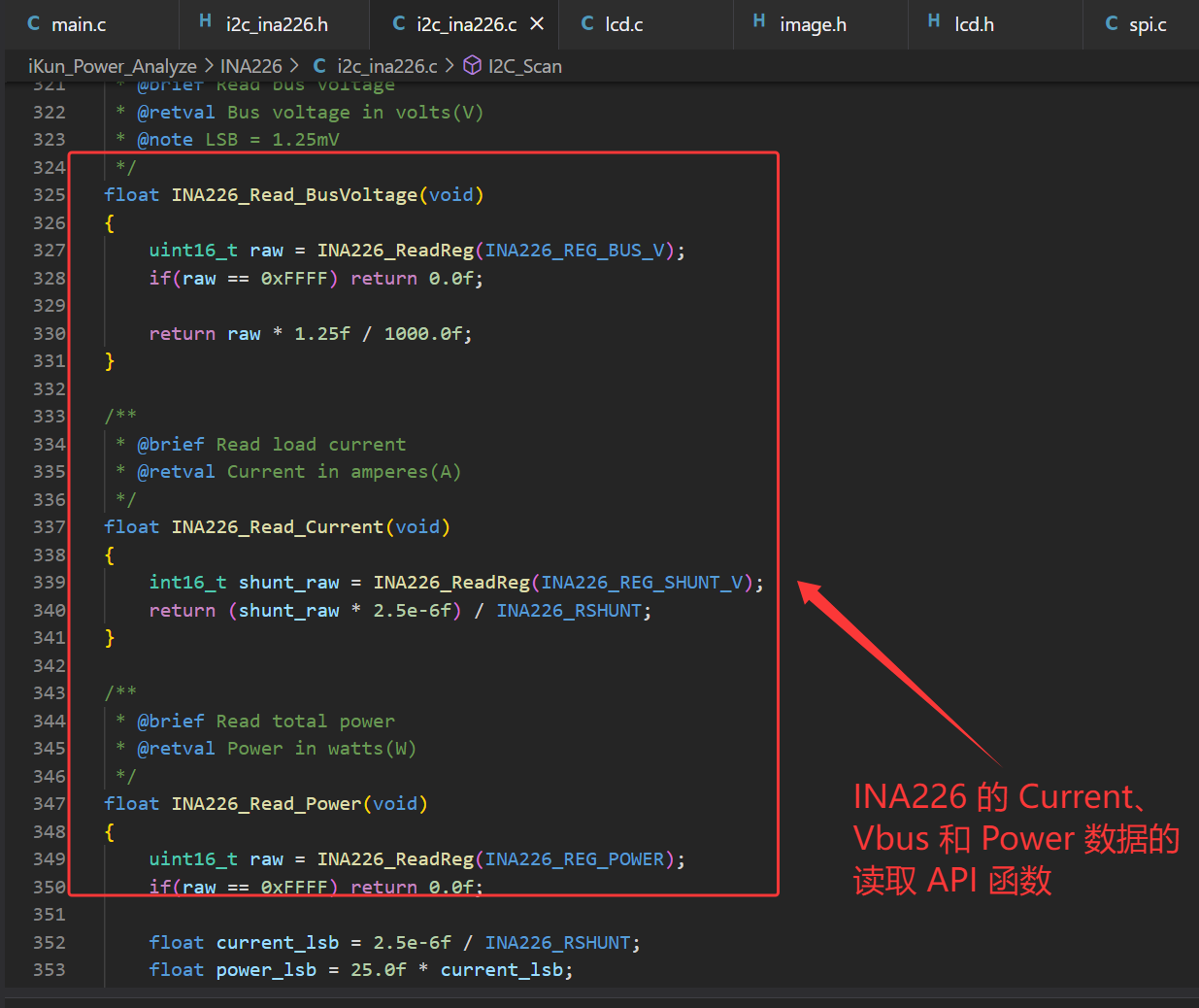
作者使用软件 I2C 驱动 INA226 电流测量芯片,使用 CH32V203C8T6 的 PA0 和 PA1 引脚进行模拟。INA226 的相关总线 Current、VBUS 和 Power 的数据测量 API 函数是很简单的,与你硬件设计保持一致即可。作者根据官方芯片手册进行编写,代码如下:
i2c_ina226.c:
/*********************************************************************
 * File Name          : i2c_ina226.c
 * Author             : 混分巨兽龙某某
 * Version            : V1.0.0
 * Date               : 2026/4/29
 * Description        : Software I2C driver and INA226 power monitor chip driver
*******************************************************************************/

#include "i2c_ina226.h"

/************************* I2C Pin Definition *************************/
#define SCL_PIN         GPIO_Pin_1
#define SDA_PIN         GPIO_Pin_0
#define SCL_PORT        GPIOA
#define SDA_PORT        GPIOA

/**
 * @brief Microsecond delay for software I2C timing
 */
#define I2C_DELAY()     { for(uint8_t i=0; i<50; i++) __NOP(); }

/**
 * @brief Set I2C SCL pin high level
 */
#define SCL_HIGH()      GPIO_SetBits(SCL_PORT, SCL_PIN)

/**
 * @brief Set I2C SCL pin low level
 */
#define SCL_LOW()       GPIO_ResetBits(SCL_PORT, SCL_PIN)

/**
 * @brief Set I2C SDA pin high level
 */
#define SDA_HIGH()      GPIO_SetBits(SDA_PORT, SDA_PIN)

/**
 * @brief Set I2C SDA pin low level
 */
#define SDA_LOW()       GPIO_ResetBits(SDA_PORT, SDA_PIN)

/**
 * @brief Read SDA pin logic level
 * @retval 1: High level, 0: Low level
 */
#define SDA_READ()      GPIO_ReadInputDataBit(SDA_PORT, SDA_PIN)

/**
 * @brief Initialize software I2C peripheral
 * @note    Use PA0 as SCL, PA1 as SDA, open-drain output mode
 */
void I2C1_Init(void)
{
    GPIO_InitTypeDef GPIO_InitStructure;

    /* Enable GPIOA clock */
    RCC_APB2PeriphClockCmd(RCC_APB2Periph_GPIOA, ENABLE);

    /* Configure SCL pin: Open drain output, 50MHz speed */
    GPIO_InitStructure.GPIO_Pin = SCL_PIN;
    GPIO_InitStructure.GPIO_Mode = GPIO_Mode_Out_OD;
    GPIO_InitStructure.GPIO_Speed = GPIO_Speed_50MHz;
    GPIO_Init(SCL_PORT, &GPIO_InitStructure);

    /* Configure SDA pin: Open drain output, 50MHz speed */
    GPIO_InitStructure.GPIO_Pin = SDA_PIN;
    GPIO_Init(SDA_PORT, &GPIO_InitStructure);

    /* Default state: SCL and SDA pull high */
    SCL_HIGH();
    SDA_HIGH();
}

/**
 * @brief Generate I2C start signal
 */
static void I2C_Start(void)
{
    SDA_HIGH();
    SCL_HIGH();
    I2C_DELAY();

    SDA_LOW();
    I2C_DELAY();

    SCL_LOW();
    I2C_DELAY();
}

/**
 * @brief Generate I2C stop signal
 */
static void I2C_Stop(void)
{
    SDA_LOW();
    SCL_HIGH();
    I2C_DELAY();

    SDA_HIGH();
    I2C_DELAY();
}

/**
 * @brief Send I2C ACK response
 */
static void I2C_SendACK(void)
{
    SDA_LOW();
    I2C_DELAY();

    SCL_HIGH();
    I2C_DELAY();

    SCL_LOW();
    SDA_HIGH();
    I2C_DELAY();
}

/**
 * @brief Send I2C NACK response
 */
static void I2C_SendNACK(void)
{
    SDA_HIGH();
    I2C_DELAY();

    SCL_HIGH();
    I2C_DELAY();

    SCL_LOW();
    I2C_DELAY();
}

/**
 * @brief Wait for ACK signal from slave device
 * @retval 1: ACK received, 0: No ACK / timeout
 */
static uint8_t I2C_WaitACK(void)
{
    uint8_t timeout = 255;

    SDA_HIGH();
    I2C_DELAY();

    SCL_HIGH();
    I2C_DELAY();

    while(SDA_READ() && timeout)
    {
        timeout--;
        I2C_DELAY();
    }

    SCL_LOW();
    I2C_DELAY();

    return (timeout > 0) ? 1 : 0;
}

/**
 * @brief Send one byte data via I2C bus
 * @param data: Byte data to transmit
 */
static void I2C_SendByte(uint8_t data)
{
    for(uint8_t i=0; i<8; i++)
    {
        if(data & 0x80)
            SDA_HIGH();
        else
            SDA_LOW();

        data <<= 1;
        I2C_DELAY();

        SCL_HIGH();
        I2C_DELAY();

        SCL_LOW();
        I2C_DELAY();
    }
    SDA_HIGH();
}

/**
 * @brief Read one byte data from I2C bus
 * @param ack: 1=Send ACK after read, 0=Send NACK after read
 * @retval Received byte data
 */
static uint8_t I2C_ReadByte(uint8_t ack)
{
    uint8_t data = 0;

    SDA_HIGH();

    for(uint8_t i=0; i<8; i++)
    {
        data <<= 1;
        SCL_HIGH();
        I2C_DELAY();

        if(SDA_READ())
            data |= 0x01;

        SCL_LOW();
        I2C_DELAY();
    }

    if(ack)
        I2C_SendACK();
    else
        I2C_SendNACK();

    return data;
}

/**
 * @brief Write 16-bit value to INA226 register
 * @param reg: INA226 register address
 * @param data: 16-bit data to write
 * @retval 1: Success, 0: Failed
 */
static uint8_t INA226_WriteReg(uint8_t reg, uint16_t data)
{
    I2C_Start();

    /* Send slave address + write bit */
    I2C_SendByte(INA226_ADDR << 1);
    if(!I2C_WaitACK())
    {
        I2C_Stop();
        return 0;
    }

    /* Send register address */
    I2C_SendByte(reg);
    if(!I2C_WaitACK())
    {
        I2C_Stop();
        return 0;
    }

    /* Send high 8-bit data */
    I2C_SendByte((data >> 8) & 0xFF);
    if(!I2C_WaitACK())
    {
        I2C_Stop();
        return 0;
    }

    /* Send low 8-bit data */
    I2C_SendByte(data & 0xFF);
    if(!I2C_WaitACK())
    {
        I2C_Stop();
        return 0;
    }

    I2C_Stop();
    return 1;
}

/**
 * @brief Read 16-bit value from INA226 register
 * @param reg: INA226 register address
 * @retval Register value, 0xFFFF means communication failed
 * @note Read high byte first, then low byte
 */
uint16_t INA226_ReadReg(uint8_t reg)
{
    uint16_t val = 0xFFFF;

    I2C_Start();
    I2C_SendByte(INA226_ADDR << 1);
    if(!I2C_WaitACK()) goto exit;

    I2C_SendByte(reg);
    if(!I2C_WaitACK()) goto exit;

    /* Restart I2C for read operation */
    I2C_Start();
    I2C_SendByte((INA226_ADDR << 1) | 0x01);
    if(!I2C_WaitACK()) goto exit;

    uint8_t high = I2C_ReadByte(1);  /* Read high byte, send ACK */
    uint8_t low  = I2C_ReadByte(0);  /* Read low byte, send NACK */

    val = ((uint16_t)high << 8) | low;

exit:
    I2C_Stop();
    return val;
}

/**
 * @brief Initialize INA226 chip
 * @note Configure working mode and calibration register for 0.1Ω shunt resistor
 */
void INA226_Init(void)
{
    /* Configure register: Continuous conversion, highest precision */
    INA226_WriteReg(INA226_REG_CONFIG, 0x4127);

    /* Calibration register for 0.1Ω shunt resistor, Current LSB = 1mA */
    uint16_t cal = 5120;
    INA226_WriteReg(INA226_REG_CALIBRATION, cal);
}

/**
 * @brief Read shunt voltage
 * @retval Shunt voltage in millivolts(mV)
 * @note LSB = 2.5uV
 */
float INA226_Read_ShuntVoltage(void)
{
    int16_t raw = INA226_ReadReg(INA226_REG_SHUNT_V);
    return raw * 2.5f / 1000.0f;
}

/**
 * @brief Read bus voltage
 * @retval Bus voltage in volts(V)
 * @note LSB = 1.25mV
 */
float INA226_Read_BusVoltage(void)
{
    uint16_t raw = INA226_ReadReg(INA226_REG_BUS_V);
    if(raw == 0xFFFF) return 0.0f;

    return raw * 1.25f / 1000.0f;
}

/**
 * @brief Read load current
 * @retval Current in amperes(A)
 */
float INA226_Read_Current(void)
{
    int16_t shunt_raw = INA226_ReadReg(INA226_REG_SHUNT_V);
    return (shunt_raw * 2.5e-6f) / INA226_RSHUNT;
}

/**
 * @brief Read total power
 * @retval Power in watts(W)
 */
float INA226_Read_Power(void)
{
    uint16_t raw = INA226_ReadReg(INA226_REG_POWER);
    if(raw == 0xFFFF) return 0.0f;

    float current_lsb = 2.5e-6f / INA226_RSHUNT;
    float power_lsb = 25.0f * current_lsb;

    return raw * power_lsb;
}

/**
 * @brief Check INA226 communication status
 * @retval 1: Chip detected and communication ok, 0: Communication error
 */
uint8_t INA226_Check(void)
{
    uint16_t id = INA226_ReadReg(0xFF); /* Read chip ID register */
    if(id == 0x2260) {
        return 1;
    } else {
        return 0;
    }
}

/**
 * @brief Scan all valid 7-bit I2C addresses on bus
 * @param found_addrs: Array to store found slave addresses
 * @retval Total number of detected I2C devices
 * @note Scan range: 0x08 ~ 0x77, skip reserved addresses
 */
uint8_t I2C_Scan(uint8_t found_addrs[])
{
    uint8_t count = 0;

    printf("Scanning I2C bus...\r\n");

    for(uint8_t addr = 0x08; addr <= 0x77; addr++)
    {
        I2C_Start();

        /* Send slave address (write operation) */
        I2C_SendByte(addr << 1);

        uint8_t timeout = 255;
        SDA_HIGH();
        I2C_DELAY();
        SCL_HIGH();
        I2C_DELAY();

        /* Poll ACK signal */
        while(SDA_READ() && timeout)
        {
            timeout--;
            I2C_DELAY();
        }

        SCL_LOW();
        I2C_Stop();

        if(timeout > 0)
        {
            if(found_addrs != NULL && count < 128)
            {
                found_addrs[count] = addr;
            }
            count++;
            printf("  Found device at 0x%02X\r\n", addr);
        }
    }

    if(count == 0)
    {
        printf("  No I2C devices found!\r\n");
    }
    else
    {
        printf("  Total %d devices found\r\n", count);
    }

    return count;
}
3.4 核心部分代码
核心代码即是将 2.4 寸 RGB_LCD 上静态化的图片与图标进行定化显示,初始化 SPI(LCD 驱动)、I2C(INA226驱动)和 USBFS(USBFS 模拟 CDC)等外设,编写相关核心数据的 API 函数进行循环读取、数据显示和数据传输即可;
main.c:
/*********************************************************************
* File Name : main.c
* Author : 混分巨兽龙某某
* Version : V1.0.0
* Date : 2026/4/29
* Description : Main program body.
*******************************************************************************/
/*
*@Note
iKun_Power_Analyze: USBSS Current Voltage Power Meter Code
pins:
I2C_SDA -- PA0
I2C_SCL -- PA1
LCD_LED -- PB9
LCD_DC -- PB10
LCD_RST -- PB11
LCD_CS -- PB12
LCD_SCK -- PB13(SPI2_SCK)
LCD_MOSI -- PB15(SPI2_MOSI)
*/
#include "debug.h"
#include "string.h"
#include "lcd.h"
#include "config.h"
#include "i2c_ina226.h"
#include "image.h"
#include <stdio.h>
#include "curve.h"
#include "ch32v20x_usbfs_device.h"
// Define curve area
CurveArea voltage_curve;
/**
* @brief Send data via USB CDC
* @param pbuf - Pointer to data buffer
* @param len - Length of data to send
* @return 1 if data sent successfully, 0 if endpoint is busy
*/
uint8_t USB_CDC_SendData(uint8_t *pbuf, uint16_t len) {
if(USBFS_Endp_Busy[DEF_UEP3] == 0) {
USBFS_Endp_DataUp(DEF_UEP3, pbuf, len, DEF_UEP_CPY_LOAD);
return 1;
}
return 0;
}
/*********************************************************************
* @fn main
*
* @brief Main program.
*
* @return none
*/
int main(void)
{
char usb_send_buf[32];
SystemCoreClockUpdate();
Delay_Init();
USART_Printf_Init(115200);
printf("SystemClk:%d\r\n", SystemCoreClock);
printf("iKun_Power_Analyze_V1.0\r\n");
printf("Author: iKun Developer\r\n");
USBFS_RCC_Init();
USBFS_Device_Init(ENABLE);
NVIC_EnableIRQ(USBFS_IRQn);
I2C1_Init();
INA226_Init();
LCD_Init();
LCD_Clear(LCD_BLACK);
Showimage(gImage_ikun);
Delay_Ms(1000);
LCD_Clear(LCD_BLACK);
Showimage_40_U(gImage_U);
Showimage_40_I(gImage_I);
Showimage_40_P(gImage_P);
Showimage_ikun(gImage_ikun2);
LCD_DrawBigChar_48x48(260, 7, 'V', LCD_RED);
LCD_DrawBigChar_48x48(260, 55, 'A', LCD_GREEN);
LCD_DrawBigChar_48x48(260, 105, 'W', LCD_YELLOW);
Curve_Init(&voltage_curve, 10, 155, 240, 80, 0, 220, LCD_RED, LCD_BLACK);
voltage_curve.grid_color = LCD_GRAY;
voltage_curve.draw_grid = 1;
while (1)
{
float bus_v = INA226_Read_BusVoltage();
float current = INA226_Read_Current();
float power = INA226_Read_Power();
int16_t current_mA = (int16_t)(current * 1000);
Curve_AddPoint(&voltage_curve, current_mA);
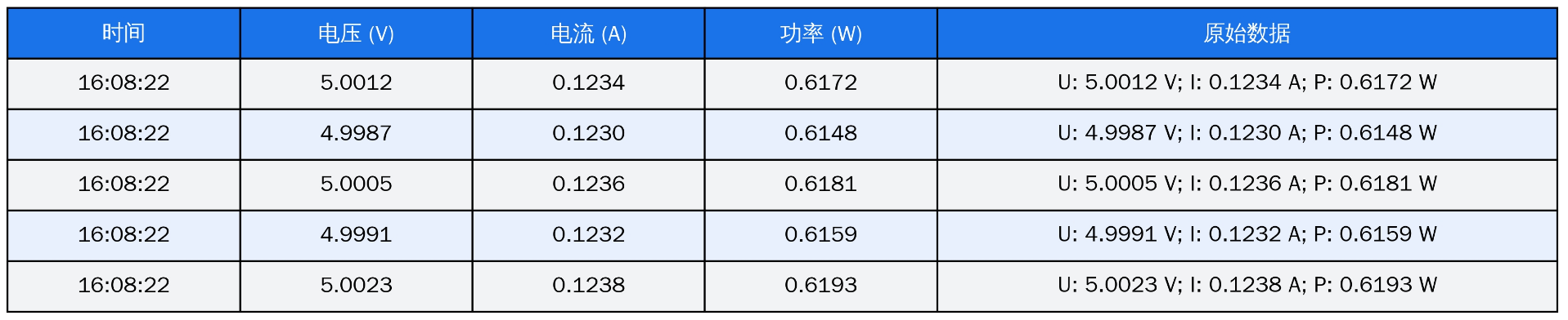
sprintf(usb_send_buf, "U: %.4f V; I: %.4f A; P: %.4f W\r\n", bus_v, current, power);
USB_CDC_SendData((uint8_t *)usb_send_buf, strlen(usb_send_buf));
LCD_ShowBigFloat_24x48(65, 5, bus_v, 4, LCD_RED, 3);
LCD_ShowBigFloat_24x48(65, 55, current, 4, LCD_GREEN, 3);
LCD_ShowBigFloat_24x48(65, 105, power, 4, LCD_YELLOW, 3);
Delay_Ms(50);
}
}
四、ikun Power Analyze 的上位机代码
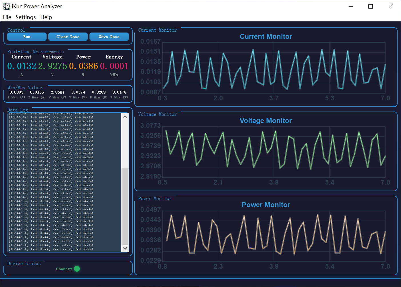
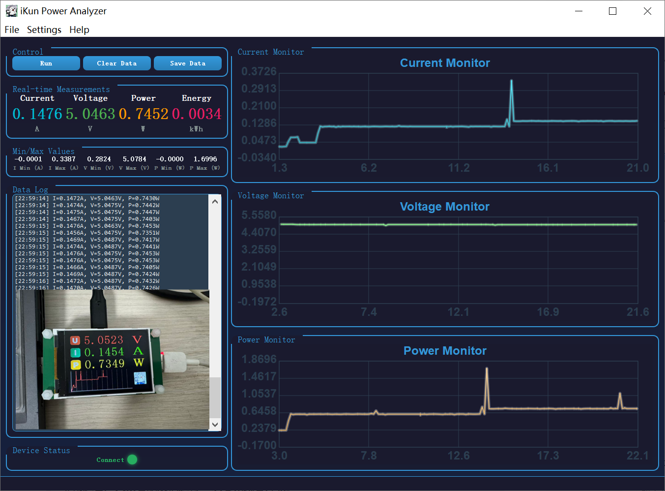
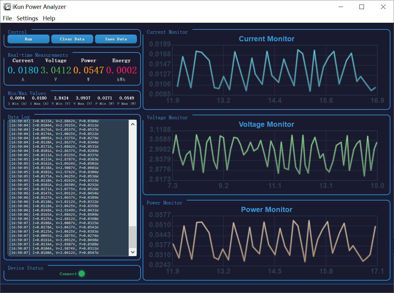
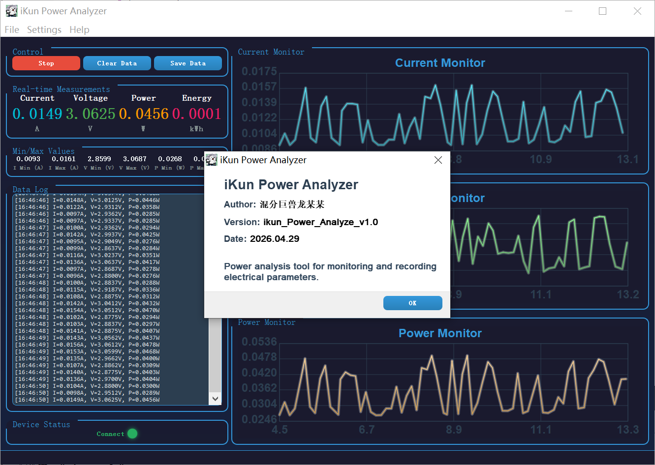
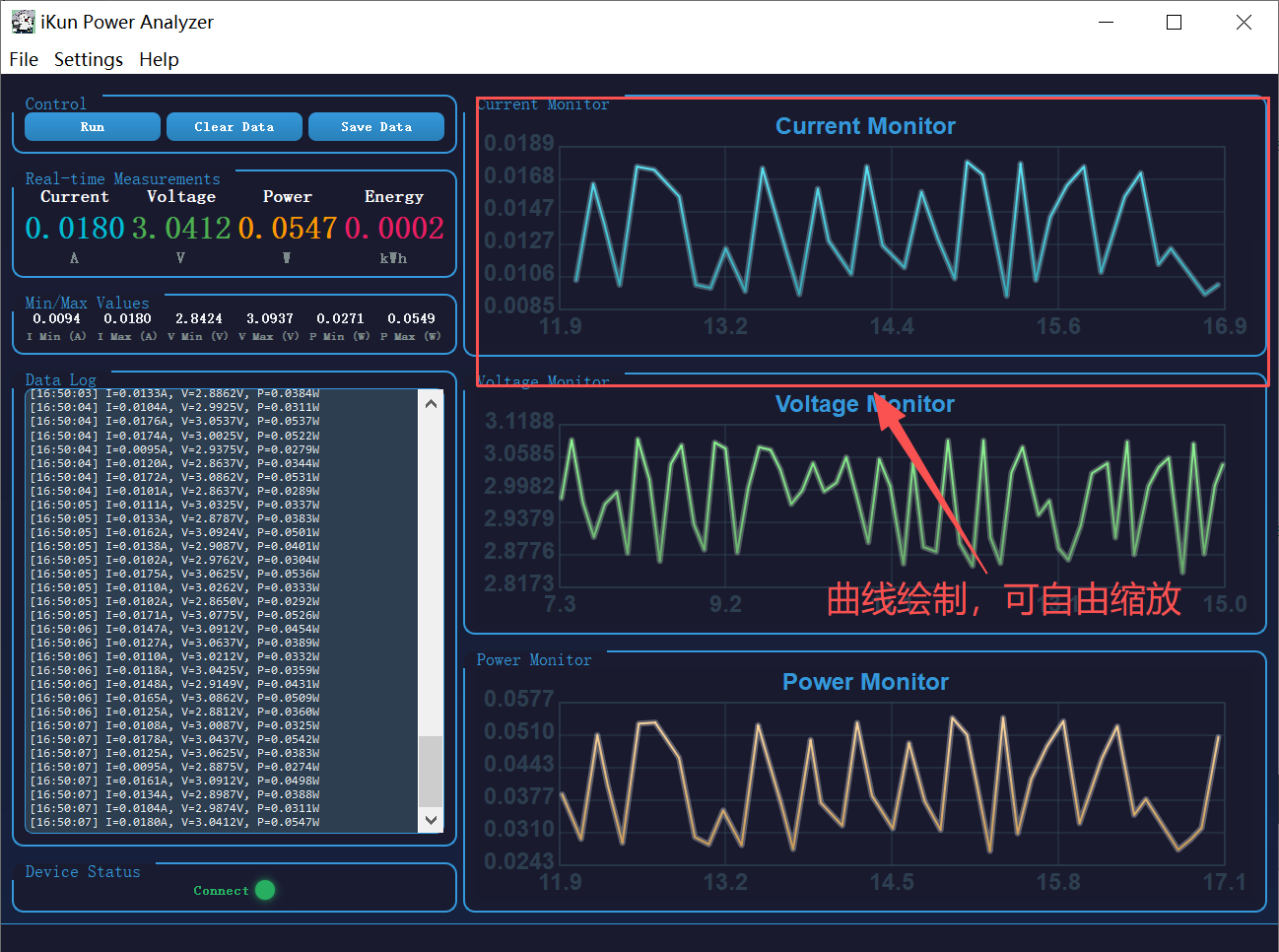
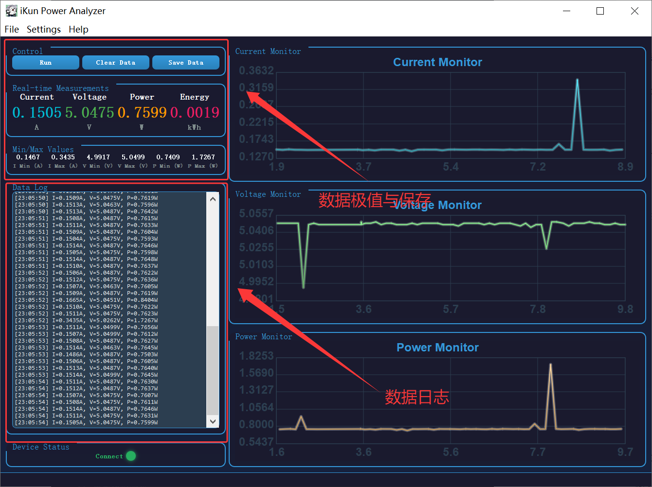
4.1 ikun Power Analyze 的 UI 布局
ikun Power Analyze 的上位机拥有如下功能:
1、ikun Power Analyze 设备自动连接上位机检测;
2、Voltage、Current 和 Power 的曲线图实时绘制;
3、Voltage、Current 和 Power 采集数据的保存与数据读档;
4、关键 Voltage、Current 和 Power 数据的记录与提示;
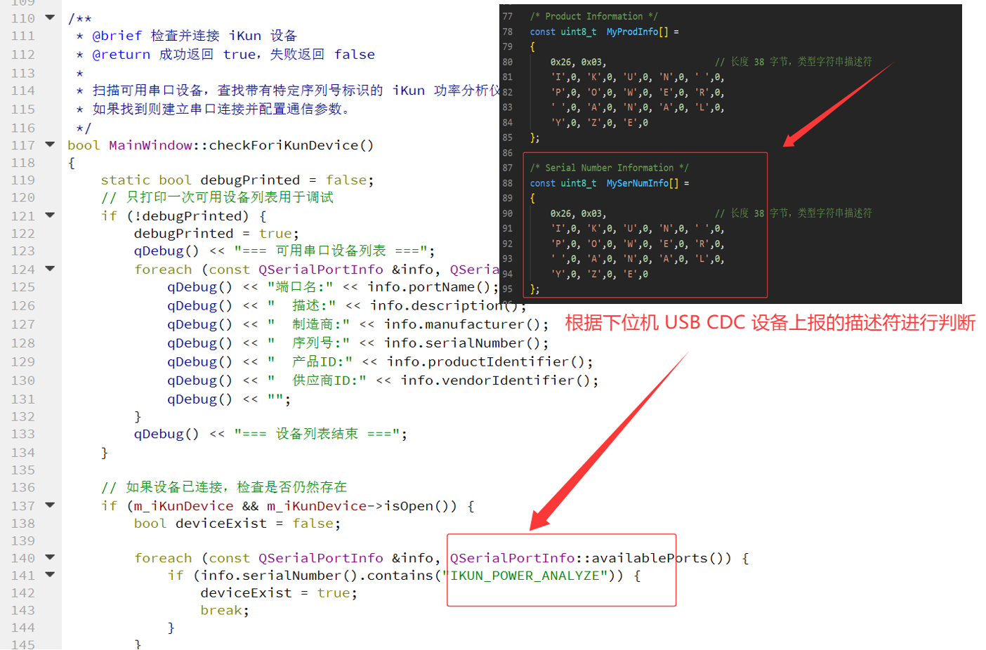
4.2 ikun Power Analyze 自动连接检测
作者这边是利用下位机 USB CDC 设备上报的字符串描述符 IKUN_POWER_ANALYZE 来判断是否连接。当判断出目标设备连接之后创建串口对象并进行绑定即可(利用定时器来进行定时判断连接状态),代码如下:
/**
 * @brief 检查并连接 iKun 设备
 * @return 成功返回 true,失败返回 false
 *
 * 扫描可用串口设备,查找带有特定序列号标识的 iKun 功率分析仪设备,
 * 如果找到则建立串口连接并配置通信参数。
 */
bool MainWindow::checkForiKunDevice()
{
    static bool debugPrinted = false;
    // 只打印一次可用设备列表用于调试
    if (!debugPrinted) {
        debugPrinted = true;
        qDebug() << "=== 可用串口设备列表 ===";
        foreach (const QSerialPortInfo &info, QSerialPortInfo::availablePorts()) {
            qDebug() << "端口名:" << info.portName();
            qDebug() << "  描述:" << info.description();
            qDebug() << "  制造商:" << info.manufacturer();
            qDebug() << "  序列号:" << info.serialNumber();
            qDebug() << "  产品ID:" << info.productIdentifier();
            qDebug() << "  供应商ID:" << info.vendorIdentifier();
            qDebug() << "";
        }
        qDebug() << "=== 设备列表结束 ===";
    }

    // 如果设备已连接,检查是否仍然存在
    if (m_iKunDevice && m_iKunDevice->isOpen()) {
        bool deviceExist = false;

        foreach (const QSerialPortInfo &info, QSerialPortInfo::availablePorts()) {
            if (info.serialNumber().contains("IKUN_POWER_ANALYZE")) {
                deviceExist = true;
                break;
            }
        }

        if (!deviceExist) {
            m_iKunDevice->close();
            m_iKunDevice->deleteLater();
            m_iKunDevice = nullptr;
            return false;
        }

        return true;
    }

    // 尝试连接新设备
    foreach (const QSerialPortInfo &info, QSerialPortInfo::availablePorts()) {
        if (info.serialNumber().contains("IKUN_POWER_ANALYZE")) {
            m_iKunDevice = new QSerialPort(info);

            // 配置串口参数
            m_iKunDevice->setBaudRate(115200);
            m_iKunDevice->setDataBits(QSerialPort::Data8);
            m_iKunDevice->setParity(QSerialPort::NoParity);
            m_iKunDevice->setStopBits(QSerialPort::OneStop);
            m_iKunDevice->setFlowControl(QSerialPort::NoFlowControl);

            if (m_iKunDevice->open(QIODevice::ReadWrite)) {
                qDebug() << "设备连接成功:" << info.portName();
                connect(m_iKunDevice, &QSerialPort::readyRead, this, &MainWindow::onSerialPortReadyRead);
                startTime = QDateTime::currentMSecsSinceEpoch();
                dataPointCount = 0;
                return true;
            } else {
                delete m_iKunDevice;
                m_iKunDevice = nullptr;
            }
        }
    }

    return false;
}
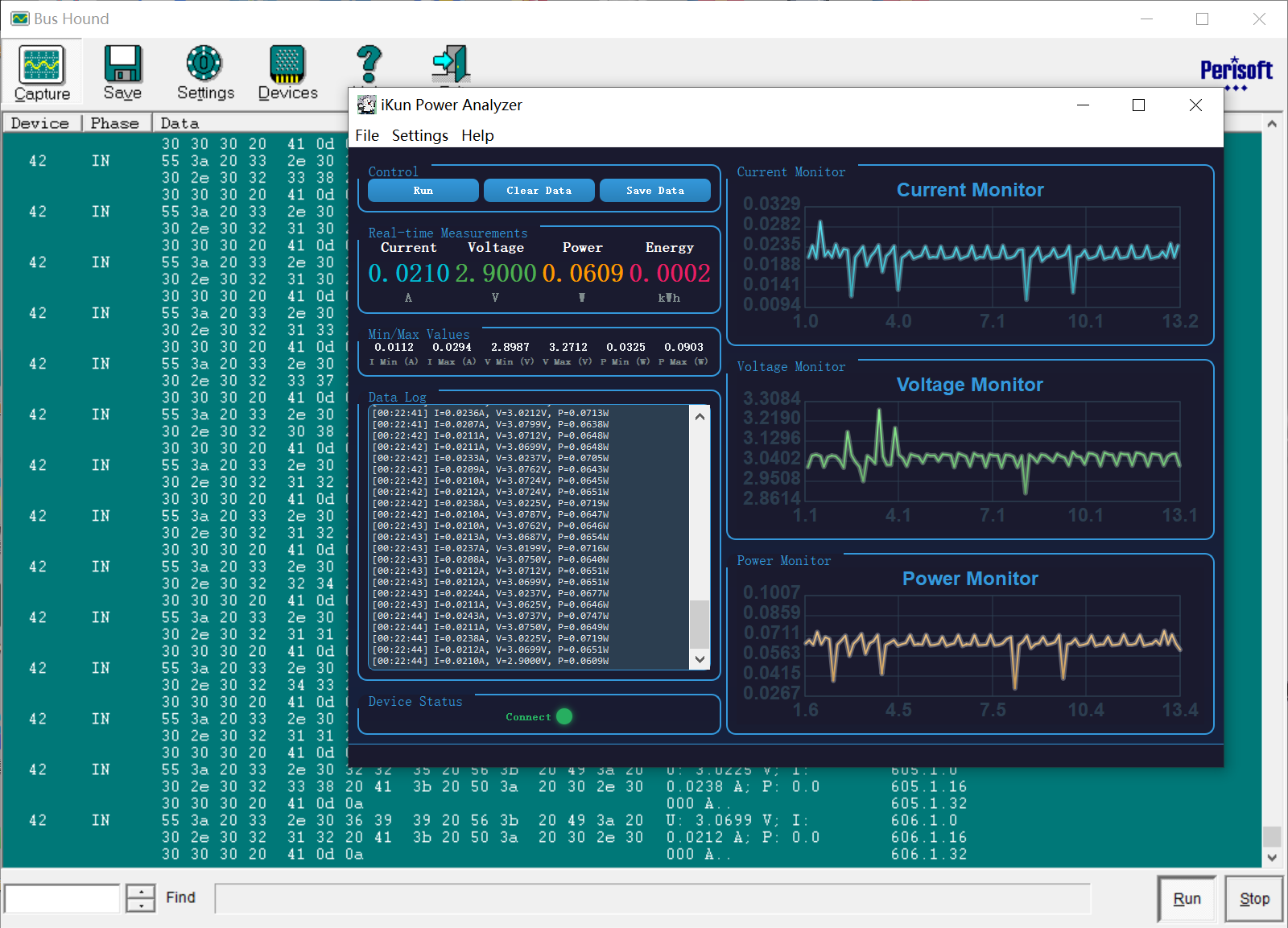
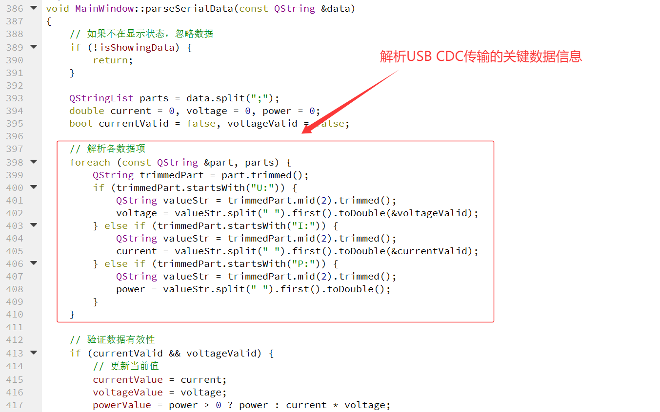
4.3 USB CDC 数据的传输
USB CDC 的数据读取:作者的上位机代码其实就是利用了 Qt Creator 库自带的 Serial 进行数据的读取操作。相比于传统的 Serial 操作,作者这边针对发送数据进行了 USB CDC 数据传输格式的解析操作。且利用得到的数据进行简单的数据统计和记录操作。
/**
* @brief 格式化数字为指定小数位数
* @param value 要格式化的数值
* @param decimals 小数位数,默认为 4
* @return 格式化后的字符串
*/
QString MainWindow::formatNumber(double value, int decimals)
{
return QString("%1").arg(value, 0, 'f', decimals);
}
/**
* @brief 串口数据就绪槽函数
*
* 当串口有数据可读时触发,读取所有可用数据并按行解析。
*/
void MainWindow::onSerialPortReadyRead()
{
// 读取所有可用数据到缓冲区
serialBuffer += m_iKunDevice->readAll();
// 按行处理数据
while (serialBuffer.contains('\n')) {
int newlineIndex = serialBuffer.indexOf('\n');
QString line = serialBuffer.left(newlineIndex).trimmed();
serialBuffer.remove(0, newlineIndex + 1);
if (!line.isEmpty()) {
parseSerialData(line);
}
}
}
/**
* @brief 解析串口数据
* @param data 接收到的串口数据字符串
*
* 解析格式为 "U: x.xxxx V; I: y.yyyy A; P: z.zzzz W" 的数据字符串,
* 提取电压、电流、功率值并更新历史数据。
*/
void MainWindow::parseSerialData(const QString &data)
{
// 如果不在显示状态,忽略数据
if (!isShowingData) {
return;
}
QStringList parts = data.split(";");
double current = 0, voltage = 0, power = 0;
bool currentValid = false, voltageValid = false;
// 解析各数据项
foreach (const QString &part, parts) {
QString trimmedPart = part.trimmed();
if (trimmedPart.startsWith("U:")) {
QString valueStr = trimmedPart.mid(2).trimmed();
voltage = valueStr.split(" ").first().toDouble(&voltageValid);
} else if (trimmedPart.startsWith("I:")) {
QString valueStr = trimmedPart.mid(2).trimmed();
current = valueStr.split(" ").first().toDouble(¤tValid);
} else if (trimmedPart.startsWith("P:")) {
QString valueStr = trimmedPart.mid(2).trimmed();
power = valueStr.split(" ").first().toDouble();
}
}
// 验证数据有效性
if (currentValid && voltageValid) {
// 更新当前值
currentValue = current;
voltageValue = voltage;
powerValue = power > 0 ? power : current * voltage;
// 更新极值
minCurrent = qMin(minCurrent, current);
maxCurrent = qMax(maxCurrent, current);
minVoltage = qMin(minVoltage, voltage);
maxVoltage = qMax(maxVoltage, voltage);
minPower = qMin(minPower, powerValue);
maxPower = qMax(maxPower, powerValue);
// 计算相对时间
qint64 currentTime = QDateTime::currentMSecsSinceEpoch();
double elapsedTime = (currentTime - startTime) / 1000.0;
// 添加到历史数据
currentHistory.append(current);
voltageHistory.append(voltage);
powerHistory.append(powerValue);
timeHistory.append(elapsedTime);
dataPointCount++;
// 限制历史数据最大数量
if (timeHistory.size() > 300) {
currentHistory.removeFirst();
voltageHistory.removeFirst();
powerHistory.removeFirst();
timeHistory.removeFirst();
}
// 添加日志
QString log = QString("[%1] I=%2A, V=%3V, P=%4W")
.arg(QTime::currentTime().toString("HH:mm:ss"))
.arg(formatNumber(current))
.arg(formatNumber(voltage))
.arg(formatNumber(powerValue));
ui->logTextEdit->append(log);
ui->logTextEdit->verticalScrollBar()->setValue(ui->logTextEdit->verticalScrollBar()->maximum());
}
}
4.4 Power 功率的曲线绘制
作者的 ikun Power Anaylze 并没有借助第 3 方库,而是手搓了一套基于 Qt 自定义的曲线图表控件 ChartWidget,纯 QWidget 自绘实现,无需第三方图表库,集成数据展示、视图缩放、鼠标拖拽平移、数据点悬停提示全套交互功能。
/**
 * @file chartwidget.cpp
 * @brief 自定义图表控件实现文件
 * @author 混分巨兽龙某某
 * @version 1.0
 * @date 2026.04.29
 *
 * 该文件实现了 ChartWidget 类的所有成员函数,包括:
 * - 构造函数和基础设置函数
 * - 数据管理函数(setData、clear、updateAutoScale)
 * - 绘制事件处理(paintEvent)
 * - 鼠标交互事件处理(wheelEvent、mousePressEvent、mouseMoveEvent、mouseReleaseEvent)
 */

#include "chartwidget.h"
#include <QPainter>
#include <QPen>
#include <QFont>
#include <QWheelEvent>
#include <QMouseEvent>
#include <algorithm>

/**
 * @brief 构造函数
 * @param parent 父窗口指针,默认为 nullptr
 *
 * 初始化图表控件,设置最小尺寸和鼠标跟踪。
 */
ChartWidget::ChartWidget(QWidget *parent) : QWidget(parent), m_color(Qt::blue),
    m_xMin(0), m_xMax(1), m_yMin(0), m_yMax(1), m_isDragging(false),
    m_hasHoverPoint(false), m_hoverIndex(-1), m_tooltipX(0), m_tooltipY(0)
{
    setMinimumSize(200, 150);
    setMouseTracking(true);
}

/**
 * @brief 设置图表标题
 * @param title 标题文本
 */
void ChartWidget::setTitle(const QString &title)
{
    m_title = title;
}

/**
 * @brief 更新自动缩放范围
 *
 * 根据当前数据自动计算并设置 X 轴和 Y 轴的显示范围,
 * 并在数据范围内添加 10% 的边距。
 */
void ChartWidget::updateAutoScale()
{
    if (m_data.isEmpty()) {
        m_xMin = 0;
        m_xMax = 1;
        m_yMin = 0;
        m_yMax = 1;
        return;
    }

    // 计算 Y 轴范围
    double minY = *std::min_element(m_data.begin(), m_data.end());
    double maxY = *std::max_element(m_data.begin(), m_data.end());
    double rangeY = maxY - minY;
    if (rangeY < 0.0001) rangeY = 1.0;
    m_yMin = minY - rangeY * 0.1;
    m_yMax = maxY + rangeY * 0.1;

    // 计算 X 轴范围
    double minX = m_time.isEmpty() ? 0 : m_time.first();
    double maxX = m_time.isEmpty() ? 1 : m_time.last();
    m_xMin = minX;
    m_xMax = maxX;
}

/**
 * @brief 设置图表数据
 * @param data Y轴数据列表
 * @param time X轴时间数据列表
 *
 * 更新图表数据并保留用户设置的缩放状态:
 * - X轴:当时间范围扩展时自动扩展,否则保持当前范围
 * - Y轴:自动扩展以显示所有数据,但不缩小当前范围
 */
void ChartWidget::setData(const QList<double> &data, const QList<double> &time)
{
    // 保存当前缩放状态
    double oldXMin = m_xMin;
    double oldXMax = m_xMax;
    double oldYMin = m_yMin;
    double oldYMax = m_yMax;

    // 获取当前最大时间
    double currentMaxX = m_time.isEmpty() ? 0 : m_time.last();

    // 更新数据
    m_data = data;
    m_time = time;

    // 处理空数据情况
    if (m_data.isEmpty()) {
        updateAutoScale();
        update();
        return;
    }

    // 计算新的数据范围
    double newMinY = *std::min_element(m_data.begin(), m_data.end());
    double newMaxY = *std::max_element(m_data.begin(), m_data.end());
    double newRangeY = newMaxY - newMinY;
    if (newRangeY < 0.0001) newRangeY = 1.0;

    double newMaxX = m_time.isEmpty() ? 1 : m_time.last();

    // 更新 X 轴范围(仅在时间扩展时)
    if (newMaxX > currentMaxX) {
        double extendAmount = newMaxX - currentMaxX;
        m_xMax += extendAmount;
    } else {
        m_xMin = oldXMin;
        m_xMax = oldXMax;
    }

    // 更新 Y 轴范围(自动扩展以显示所有数据)
    double paddingY = newRangeY * 0.1;
    double autoMinY = newMinY - paddingY;
    double autoMaxY = newMaxY + paddingY;

    m_yMin = qMin(oldYMin, autoMinY);
    m_yMax = qMax(oldYMax, autoMaxY);

    // 触发重绘
    update();
}

/**
 * @brief 设置曲线颜色
 * @param color 曲线颜色
 */
void ChartWidget::setColor(const QColor &color)
{
    m_color = color;
}

/**
 * @brief 设置Y轴标签
 * @param label Y轴标签文本
 */
void ChartWidget::setYLabel(const QString &label)
{
    m_yLabel = label;
}

/**
 * @brief 清除图表数据
 *
 * 清空所有数据并重置显示范围。
 */
void ChartWidget::clear()
{
    m_data.clear();
    m_time.clear();
    updateAutoScale();
    update();
}

/**
 * @brief 重置视图为自动缩放状态
 *
 * 将图表视图重置为自动缩放模式,显示所有数据。
 */
void ChartWidget::resetView()
{
    updateAutoScale();
    update();
}

/**
 * @brief 重绘事件处理
 * @param event 重绘事件
 *
 * 绘制图表的各个组成部分:
 * - 背景
 * - 标题
 * - 网格线
 * - X轴和Y轴刻度
 * - 数据曲线(带渐变和发光效果)
 * - 悬停提示框
 */
void ChartWidget::paintEvent(QPaintEvent *event)
{
    Q_UNUSED(event);

    QPainter painter(this);
    painter.setRenderHint(QPainter::Antialiasing);

    // 定义边距
    int leftMargin = 85;
    int rightMargin = 30;
    int topMargin = 35;
    int bottomMargin = 35;

    // 计算图表区域尺寸
    int chartWidth = width() - leftMargin - rightMargin;
    int chartHeight = height() - topMargin - bottomMargin;

    // 绘制背景
    painter.fillRect(rect(), QColor(26, 26, 46));

    // 绘制标题
    painter.setPen(QColor(52, 152, 219));
    painter.setFont(QFont("Arial", 12, QFont::Bold));
    int titleWidth = painter.fontMetrics().width(m_title);
    painter.drawText(width() / 2 - titleWidth / 2, 22, m_title);

    // 处理空数据情况
    if (m_data.isEmpty()) {
        painter.setPen(QColor(127, 140, 141));
        painter.setFont(QFont("Arial", 10));
        painter.drawText(width() / 2 - 40, height() / 2, "No data");
        return;
    }

    // 计算数据范围
    double rangeY = m_yMax - m_yMin;
    if (rangeY < 0.0001) rangeY = 1.0;

    double rangeX = m_xMax - m_xMin;
    if (rangeX < 0.0001) rangeX = 1.0;

    // 绘制图表边框
    painter.setPen(QColor(44, 62, 80));
    painter.setBrush(Qt::NoBrush);
    painter.drawRect(leftMargin, topMargin, chartWidth, chartHeight);

    // 绘制 Y 轴网格线和刻度
    painter.setPen(QColor(44, 62, 80));
    for (int i = 0; i <= 5; i++) {
        int y = topMargin + (chartHeight * i) / 5;
        painter.drawLine(leftMargin, y, width() - rightMargin, y);

        double value = m_yMax - ((m_yMax - m_yMin) * i) / 5;
        QString label = QString("%1").arg(value, 0, 'f', 4);
        int labelWidth = painter.fontMetrics().width(label);
        painter.drawText(leftMargin - labelWidth - 5, y + 4, label);
    }

    // 绘制 X 轴网格线和刻度
    painter.setPen(QColor(44, 62, 80));
    for (int i = 0; i <= 4; i++) {
        int x = leftMargin + (chartWidth * i) / 4;
        painter.drawLine(x, topMargin, x, height() - bottomMargin);

        double value = m_xMin + ((m_xMax - m_xMin) * i) / 4;
        QString label = QString("%1").arg(value, 0, 'f', 1);
        int labelWidth = painter.fontMetrics().width(label);
        painter.drawText(x - labelWidth / 2, height() - 10, label);
    }

    // 创建渐变画笔
    QLinearGradient gradient(leftMargin, topMargin, leftMargin, height() - bottomMargin);
    gradient.setColorAt(0, m_color.lighter(150));
    gradient.setColorAt(1, m_color.darker(150));

    QPen linePen;
    linePen.setBrush(gradient);
    linePen.setWidth(2);
    linePen.setCapStyle(Qt::RoundCap);
    linePen.setJoinStyle(Qt::RoundJoin);
    painter.setPen(linePen);

    // 绘制数据曲线
    if (m_data.size() >= 2) {
        QPainterPath path;
        bool pathStarted = false;

        for (int i = 0; i < m_data.size(); i++) {
            double t = m_time[i];
            if (t >= m_xMin && t <= m_xMax) {
                double x = leftMargin + ((t - m_xMin) / rangeX) * chartWidth;
                double y = topMargin + ((m_yMax - m_data[i]) / rangeY) * chartHeight;

                if (!pathStarted) {
                    path.moveTo(x, y);
                    pathStarted = true;
                } else {
                    path.lineTo(x, y);
                }
            }
        }

        // 绘制主曲线
        painter.strokePath(path, linePen);

        // 绘制发光效果
        QPen glowPen(m_color.lighter(200), 6);
        glowPen.setCapStyle(Qt::RoundCap);
        glowPen.setJoinStyle(Qt::RoundJoin);
        painter.setPen(glowPen);
        painter.setOpacity(0.3);
        painter.strokePath(path, glowPen);
        painter.setOpacity(1.0);
    }

    // 绘制悬停提示
    if (m_hasHoverPoint && m_hoverIndex >= 0) {
        double t = m_time[m_hoverIndex];
        double val = m_data[m_hoverIndex];
        double x = leftMargin + ((t - m_xMin) / rangeX) * chartWidth;
        double y = topMargin + ((m_yMax - val) / rangeY) * chartHeight;

        // 绘制悬停点指示器
        painter.setBrush(QColor(255, 255, 255, 20));
        painter.setPen(Qt::NoPen);
        painter.drawEllipse(QPointF(x, y), 8, 8);

        painter.setBrush(QColor(255, 255, 255));
        painter.drawEllipse(QPointF(x, y), 4, 4);

        // 绘制提示框
        QString tooltip = QString("X: %1 s\nY: %2").arg(t, 0, 'f', 4).arg(val, 0, 'f', 4);
        QRect tooltipRect = painter.fontMetrics().boundingRect(tooltip);
        tooltipRect.adjust(-5, -5, 5, 5);

        // 计算提示框位置(避免超出边界)
        int tooltipX = x > width() / 2 ? leftMargin + 5 : width() - rightMargin - tooltipRect.width() - 5;
        int tooltipY = y > height() / 2 ? topMargin + 5 : height() - bottomMargin - tooltipRect.height() - 5;

        // 绘制提示框背景
        painter.setBrush(QColor(44, 62, 80));
        painter.setPen(QColor(52, 152, 219));
        painter.drawRect(tooltipX, tooltipY, tooltipRect.width(), tooltipRect.height());

        // 绘制提示框文字
        painter.setPen(QColor(255, 255, 255));
        painter.setFont(QFont("Arial", 8));
        painter.drawText(tooltipX + 5, tooltipY + 12, tooltip);
    }
}

/**
 * @brief 滚轮事件处理(缩放)
 * @param event 滚轮事件
 *
 * 实现以鼠标位置为中心的缩放功能:
 * - 滚轮向上:放大图表
 * - 滚轮向下:缩小图表
 * - 限制缩放范围,避免过度缩放
 */
void ChartWidget::wheelEvent(QWheelEvent *event)
{
    if (m_data.isEmpty()) return;

    // 定义边距
    int leftMargin = 85;
    int rightMargin = 30;
    int topMargin = 35;
    int bottomMargin = 35;

    int chartWidth = width() - leftMargin - rightMargin;
    int chartHeight = height() - topMargin - bottomMargin;

    // 获取鼠标位置
    QPoint mousePos = event->pos();
    double x = mousePos.x();
    double y = mousePos.y();

    // 检查鼠标是否在图表区域内
    if (x < leftMargin || x > width() - rightMargin || y < topMargin || y > height() - bottomMargin) {
        return;
    }

    // 将屏幕坐标转换为图表坐标
    double chartX = (x - leftMargin) / (double)chartWidth;
    double chartY = (y - topMargin) / (double)chartHeight;

    // 将图表坐标转换为数据坐标
    double dataX = m_xMin + chartX * (m_xMax - m_xMin);
    double dataY = m_yMax - chartY * (m_yMax - m_yMin);

    // 计算缩放因子(向上放大,向下缩小)
    double zoomFactor = event->delta() > 0 ? 0.7 : 1.3;

    // 计算新的范围
    double newRangeX = (m_xMax - m_xMin) * zoomFactor;
    double newRangeY = (m_yMax - m_yMin) * zoomFactor;

    // 获取数据边界
    double minTime = m_time.isEmpty() ? 0 : m_time.first();
    double maxTime = m_time.isEmpty() ? 1 : m_time.last();
    double minDataY = *std::min_element(m_data.begin(), m_data.end());
    double maxDataY = *std::max_element(m_data.begin(), m_data.end());
    double dataRangeY = maxDataY - minDataY;
    if (dataRangeY < 0.0001) dataRangeY = 1.0;

    // 限制缩放范围
    double minAllowedRangeX = 0.01 * (maxTime - minTime);
    double maxAllowedRangeX = 2.0 * (maxTime - minTime);
    double minAllowedRangeY = 0.01 * dataRangeY;
    double maxAllowedRangeY = 2.0 * dataRangeY;

    newRangeX = qBound(minAllowedRangeX, newRangeX, maxAllowedRangeX);
    newRangeY = qBound(minAllowedRangeY, newRangeY, maxAllowedRangeY);

    // 计算新的边界(以鼠标位置为中心)
    double ratioX = (dataX - m_xMin) / (m_xMax - m_xMin);
    double ratioY = (dataY - m_yMin) / (m_yMax - m_yMin);

    m_xMin = dataX - ratioX * newRangeX;
    m_xMax = dataX + (1 - ratioX) * newRangeX;
    m_yMin = dataY - ratioY * newRangeY;
    m_yMax = dataY + (1 - ratioY) * newRangeY;

    // 限制在数据范围内
    m_xMin = qMax(m_xMin, minTime);
    m_xMax = qMin(m_xMax, maxTime);
    m_yMin = qMax(m_yMin, minDataY - dataRangeY * 0.2);
    m_yMax = qMin(m_yMax, maxDataY + dataRangeY * 0.2);

    // 触发重绘
    update();
    event->accept();
}

/**
 * @brief 鼠标按下事件处理
 * @param event 鼠标事件
 *
 * 记录拖动开始状态和鼠标位置。
 */
void ChartWidget::mousePressEvent(QMouseEvent *event)
{
    if (event->button() == Qt::LeftButton) {
        m_isDragging = true;
        m_lastMousePos = event->pos();
        m_hasHoverPoint = false;
    }
    QWidget::mousePressEvent(event);
}

/**
 * @brief 鼠标移动事件处理(拖动/悬停)
 * @param event 鼠标事件
 *
 * 处理两种情况:
 * - 拖动状态:根据鼠标位移平移图表
 * - 非拖动状态:检测鼠标悬停在哪个数据点上
 */
void ChartWidget::mouseMoveEvent(QMouseEvent *event)
{
    int leftMargin = 85;
    int rightMargin = 30;
    int topMargin = 35;
    int bottomMargin = 35;

    int chartWidth = width() - leftMargin - rightMargin;
    int chartHeight = height() - topMargin - bottomMargin;

    if (m_isDragging) {
        // 拖动模式:计算位移并平移图表
        QPoint delta = event->pos() - m_lastMousePos;

        // 将屏幕位移转换为数据位移
        double xDelta = delta.x() / (double)chartWidth * (m_xMax - m_xMin);
        double yDelta = delta.y() / (double)chartHeight * (m_yMax - m_yMin);

        // 更新数据范围
        m_xMin -= xDelta;
        m_xMax -= xDelta;
        m_yMin += yDelta;
        m_yMax += yDelta;

        // 获取数据边界
        double minTime = m_time.isEmpty() ? 0 : m_time.first();
        double maxTime = m_time.isEmpty() ? 1 : m_time.last();

        // 限制 X 轴范围
        if (m_xMin < minTime) {
            m_xMax += minTime - m_xMin;
            m_xMin = minTime;
        }
        if (m_xMax > maxTime) {
            m_xMin -= m_xMax - maxTime;
            m_xMax = maxTime;
        }

        // 更新鼠标位置
        m_lastMousePos = event->pos();
        update();
    } else {
        // 悬停模式:查找最近的数据点
        QPoint mousePos = event->pos();
        double x = mousePos.x();
        double y = mousePos.y();

        // 检查鼠标是否在图表区域内
        if (x >= leftMargin && x <= width() - rightMargin && y >= topMargin && y <= height() - bottomMargin) {
            // 转换为图表坐标
            double chartX = (x - leftMargin) / (double)chartWidth;
            double chartY = (y - topMargin) / (double)chartHeight;

            // 转换为数据坐标
            double dataX = m_xMin + chartX * (m_xMax - m_xMin);
            double dataY = m_yMax - chartY * (m_yMax - m_yMin);

            // 查找最近的数据点
            double minDist = 1000000;
            int closestIndex = -1;

            for (int i = 0; i < m_data.size(); i++) {
                double t = m_time[i];
                if (t >= m_xMin && t <= m_xMax) {
                    double dist = qAbs(t - dataX) + qAbs(m_data[i] - dataY);
                    if (dist < minDist) {
                        minDist = dist;
                        closestIndex = i;
                    }
                }
            }

            // 设置悬停状态
            if (closestIndex >= 0 && minDist < 0.5) {
                m_hoverIndex = closestIndex;
                m_hasHoverPoint = true;
            } else {
                m_hasHoverPoint = false;
                m_hoverIndex = -1;
            }
            update();
        } else {
            m_hasHoverPoint = false;
            update();
        }
    }
    QWidget::mouseMoveEvent(event);
}

/**
 * @brief 鼠标释放事件处理
 * @param event 鼠标事件
 *
 * 结束拖动状态。
 */
void ChartWidget::mouseReleaseEvent(QMouseEvent *event)
{
    if (event->button() == Qt::LeftButton) {
        m_isDragging = false;
    }
    QWidget::mouseReleaseEvent(event);
}
4.5 附加功能代码
作者的 ikun Power Analyze 还额外附赠了其余的一些功能,例如:数据日志附加功能、极值统计、累计电能计算、一键清空数据、作者与软件信息和 CSV 数据导出等;
/**
 * @brief 定时器更新槽函数
 *
 * 定期更新界面显示,包括:
 * - 更新数值显示
 * - 更新极值显示
 * - 更新能量累计
 * - 更新图表
 * - 更新连接状态
 */
void MainWindow::onTimerUpdate()
{
    // 检查设备连接状态
    bool isConnected = checkForiKunDevice();

    // 更新数值显示
    ui->currentValueLabel->setText(formatNumber(currentValue));
    ui->voltageValueLabel->setText(formatNumber(voltageValue));
    ui->powerValueLabel->setText(formatNumber(powerValue));
    ui->energyValueLabel->setText(formatNumber(energyValue));

    // 更新极值显示
    ui->minCurrentLabel->setText(formatNumber(minCurrent));
    ui->maxCurrentLabel->setText(formatNumber(maxCurrent));
    ui->minVoltageLabel->setText(formatNumber(minVoltage));
    ui->maxVoltageLabel->setText(formatNumber(maxVoltage));
    ui->minPowerLabel->setText(formatNumber(minPower));
    ui->maxPowerLabel->setText(formatNumber(maxPower));

    // 累计能量并更新图表
    if (dataPointCount > 0) {
        energyValue += powerValue / 3600.0 / 10.0;
        updateCharts();
    }

    // 更新连接状态显示
    QString status = isConnected ? "Connect" : "Disconnected";
    ui->connectionStatusLabel->setText(status);
    ui->connectionStatusLabel->setStyleSheet(isConnected
        ? "color: #27ae60; font-size: 14px; font-weight: bold;"
        : "color: #e74c3c; font-size: 14px; font-weight: bold;");

    // 更新连接状态球颜色
    QString ballColor = isConnected ? "#27ae60" : "#e74c3c";
    ui->connectionStatusBall->setStyleSheet(QString("border-radius: 10px; background-color: %1;").arg(ballColor));
    if (ballShadowEffect) {
        ballShadowEffect->setColor(QColor(ballColor));
    }
}

/**
 * @brief 更新图表数据
 *
 * 将历史数据同步到三个图表控件中。
 */
void MainWindow::updateCharts()
{
    currentChart->setData(currentHistory, timeHistory);
    voltageChart->setData(voltageHistory, timeHistory);
    powerChart->setData(powerHistory, timeHistory);
}

/**
 * @brief 清除按钮点击槽函数
 *
 * 清除所有历史数据和图表显示,重置统计变量。
 */
void MainWindow::onClearButtonClicked()
{
    // 清除日志
    ui->logTextEdit->clear();

    // 清除历史数据
    currentHistory.clear();
    voltageHistory.clear();
    powerHistory.clear();
    timeHistory.clear();
    dataPointCount = 0;
    startTime = QDateTime::currentMSecsSinceEpoch();
    energyValue = 0;

    // 重置极值
    minCurrent = 99999; maxCurrent = -99999;
    minVoltage = 99999; maxVoltage = -99999;
    minPower = 99999; maxPower = -99999;

    // 清除图表
    currentChart->clear();
    voltageChart->clear();
    powerChart->clear();

    // 显示状态消息
    ui->statusBar->showMessage("Data cleared", 3000);
}

/**
 * @brief 保存按钮点击槽函数
 *
 * 将历史数据保存为 CSV 文件,包含时间、电流、电压、功率四列。
 */
void MainWindow::onSaveButtonClicked()
{
    QString fileName = QFileDialog::getSaveFileName(this, "Save Data",
        QDateTime::currentDateTime().toString("yyyyMMdd_HHmmss") + "_power_data.csv",
        "CSV Files (*.csv)");

    if (!fileName.isEmpty()) {
        QFile file(fileName);
        if (file.open(QIODevice::WriteOnly | QIODevice::Text)) {
            QTextStream out(&file);
            // 写入表头
            out << "Time(s),Current(A),Voltage(V),Power(W)\n";

            // 写入数据
            for (int i = 0; i < timeHistory.size(); i++) {
                out << formatNumber(timeHistory[i]) << ","
                    << formatNumber(currentHistory[i]) << ","
                    << formatNumber(voltageHistory[i]) << ","
                    << formatNumber(powerHistory[i]) << "\n";
            }

            file.close();
            ui->statusBar->showMessage("Data saved successfully", 3000);
        } else {
            QMessageBox::critical(this, "Error", "Failed to save file!");
        }
    }
}

/**
 * @brief 显示/停止按钮点击槽函数
 *
 * 控制数据显示的开始和停止,切换按钮文字和颜色。
 */
void MainWindow::onShowButtonClicked()
{
    isShowingData = !isShowingData;

    if (isShowingData) {
        ui->showButton->setText("Stop");
        ui->showButton->setStyleSheet("background-color: #e74c3c; color: white;");
    } else {
        ui->showButton->setText("Run");
        ui->showButton->setStyleSheet("background-color: #27ae60; color: white;");
    }
}

/**
 * @brief 文件菜单 - 保存数据槽函数
 *
 * 响应 File -> Save Data 菜单操作,调用保存功能。
 */
void MainWindow::on_actionSave_Data_triggered()
{
    onSaveButtonClicked();
}

/**
 * @brief 文件菜单 - 退出槽函数
 *
 * 响应 File -> Exit 菜单操作,关闭应用程序。
 */
void MainWindow::on_actionExit_triggered()
{
    close();
}

/**
 * @brief 设置菜单 - 端口设置槽函数
 *
 * 响应 Settings -> Port Settings 菜单操作,显示端口配置信息对话框。
 */
void MainWindow::on_actionPort_Settings_triggered()
{
    QString portInfo;
    if (m_iKunDevice && m_iKunDevice->isOpen()) {
        portInfo = QString(
            "<!DOCTYPE HTML PUBLIC \"-//W3C//DTD HTML 4.0//EN\" \"http://www.w3.org/TR/REC-html40/strict.dtd\">"
            "<html><head><meta name=\"qrichtext\" content=\"1\" /><style type=\"text/css\">"
            "p { white-space: pre-wrap; color: #000000; font-size: 14px; }"
            "strong { color: #2c3e50; }"
            "</style></head><body style=\"font-family: Arial;\">"
            "<p><strong>Port:</strong> %1</p>"
            "<p><strong>Baud Rate:</strong> %2</p>"
            "<p><strong>Data Bits:</strong> 8</p>"
            "<p><strong>Parity:</strong> None</p>"
            "<p><strong>Stop Bits:</strong> 1</p>"
            "<p><strong>Flow Control:</strong> None</p>"
            "</body></html>"
        ).arg(m_iKunDevice->portName()).arg(m_iKunDevice->baudRate());
    } else {
        portInfo = QString(
            "<!DOCTYPE HTML PUBLIC \"-//W3C//DTD HTML 4.0//EN\" \"http://www.w3.org/TR/REC-html40/strict.dtd\">"
            "<html><head><meta name=\"qrichtext\" content=\"1\" /><style type=\"text/css\">"
            "p { color: #000000; font-size: 14px; }"
            "</style></head><body style=\"font-family: Arial;\">"
            "<p>No device connected</p>"
            "</body></html>"
        );
    }

    QMessageBox::information(this, "Port Settings", portInfo);
}

/**
 * @brief 帮助菜单 - 关于槽函数
 *
 * 响应 Help -> About 菜单操作,显示关于对话框,包含作者、版本、日期等信息。
 */
void MainWindow::on_actionAbout_triggered()
{
    QString aboutText = QString(
        "<!DOCTYPE HTML PUBLIC \"-//W3C//DTD HTML 4.0//EN\" \"http://www.w3.org/TR/REC-html40/strict.dtd\">"
        "<html><head><meta name=\"qrichtext\" content=\"1\" /><style type=\"text/css\">"
        "p, li { white-space: pre-wrap; color: #000000; }"
        "h2 { color: #2c3e50; font-weight: bold; }"
        "strong { color: #2c3e50; }"
        "</style></head><body style=\"font-family: Arial;\">"
        "<h2>iKun Power Analyzer</h2>"
        "<p><strong>Author:</strong> 混分巨兽龙某某</p>"
        "<p><strong>Version:</strong> ikun_Power_Analyze_v1.0</p>"
        "<p><strong>Date:</strong> 2026.04.29</p>"
        "<p><br/><span style=\"color: #34495e;\">Power analysis tool for monitoring and recording electrical parameters.</span></p>"
        "</body></html>"
    );

    QMessageBox::about(this, "About iKun Power Analyzer", aboutText);
}
五、项目演示
作者将本篇博客制作的 ikun Power Analyze 与市面上主流 USB 功率计进行对比,保证被测对象与工况的一致,测试结果如下:
测试项目案例(1):
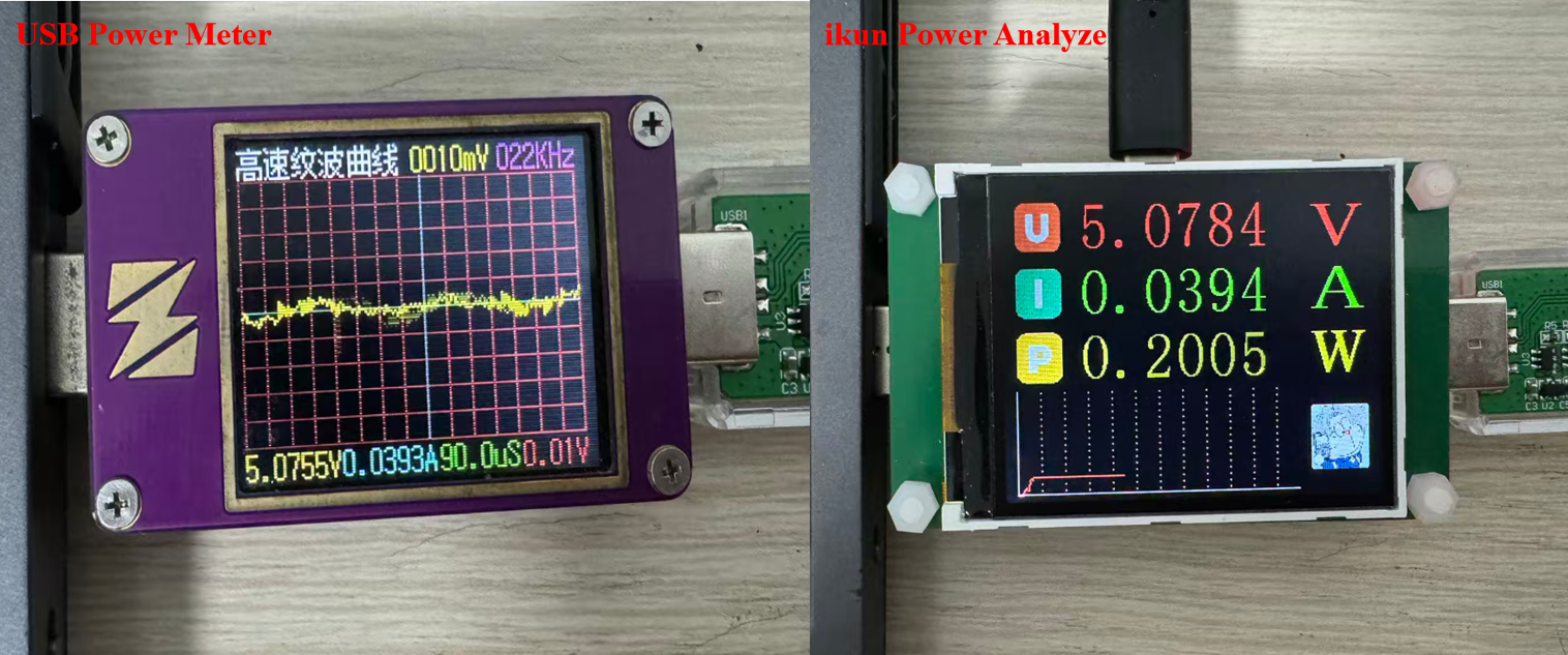
测试项目案例(2):

六、代码开源
代码地址: 基于沁恒CH32V203与INA226的USBSS功率计项目资料资源-CSDN下载
如果积分不够的朋友,点波关注,评论区留下邮箱,作者无偿提供源码和后续问题解答。求求啦关注一波吧 !!!

AtomGit 是由开放原子开源基金会联合 CSDN 等生态伙伴共同推出的新一代开源与人工智能协作平台。平台坚持“开放、中立、公益”的理念,把代码托管、模型共享、数据集托管、智能体开发体验和算力服务整合在一起,为开发者提供从开发、训练到部署的一站式体验。
更多推荐

 9
9 0
0- 0


 已为社区贡献3条内容

所有评论(0)